Process and assembly for non-destructive surface inspections

Inactive Publication Date: 2006-09-05
KLA TENCOR CORP
View PDF32 Cites 12 Cited by
  • Summary
  • Abstract
  • Description
  • Claims
  • Application Information

AI Technical Summary

Benefits of technology

[0029]As noted above, it is difficult for prior art systems to detect small anomalies such as small particles and defects. Small particles or defects scatter light at large angles to the normal direction of the surface when the surface is illuminated in the normal direction. In normal illumination prior art systems where the light scattered by the surface is collected by a lens system where the axis of the lens system is along the normal direction, the lens system will collect only a small portion of the light scattered by such small anomalies. If large anomalies such as particles or surface defects are also present in addition to the small anomalies, the scattering from such large anomalies will be at much higher intensities compared to and will mask those caused by the small anomalies so that the small anomalies become difficult or impossible to detect. One aspect of the invention is based on the recognition that, since the scattering from the large anomalies is at much higher intensities at specular or near specular collection angles (that is, small angles to the normal) than at large collection angles whereas the scattering from small anomalies have intensities which are more evenly distributed in all directions to the normal, with most of the energy contained in the larger angles. The detection of the small anomalies can therefore be much enhanced by using an ellipsoidal mirrored surface to collect light scattered at relatively large collection angles to the normal and avoiding light scattered at specular or near specular directions.
[0031]When it is known that the surface scattering or haze level is low, and that there are few large defects or point-anomalies, detection sensitivity for small anomalies can be further enhanced by adding to the ellipsoidal mirrored surface of the above apparatus a lens assembly that collects light scattered in a small angle region near the specular direction and focuses the collected light to the same area as the ellipsoidal mirrored surface.
[0036]As indicated above, the requirements for detection sensitivity are becoming more and more stringent. For such purpose, it is desirable to focus the illuminating beam onto a small spot on the inspected surface, such as one no larger than 50 microns in dimensions in any direction on the surface. This will enhance signal-to-noise ratio.

Problems solved by technology

As noted above, it is difficult for prior art systems to detect small anomalies such as small particles and defects.
If large anomalies such as particles or surface defects are also present in addition to the small anomalies, the scattering from such large anomalies will be at much higher intensities compared to and will mask those caused by the small anomalies so that the small anomalies become difficult or impossible to detect.
On the other hand, if the detector means is optimized for detecting the high intensity light scattered by larger particles, it is not optimized to detect low intensity light scattered by the smaller particles.

Method used


Image

  • Process and assembly for non-destructive surface inspections
  • Process and assembly for non-destructive surface inspections
  • Process and assembly for non-destructive surface inspections

Examples


Embodiment Construction

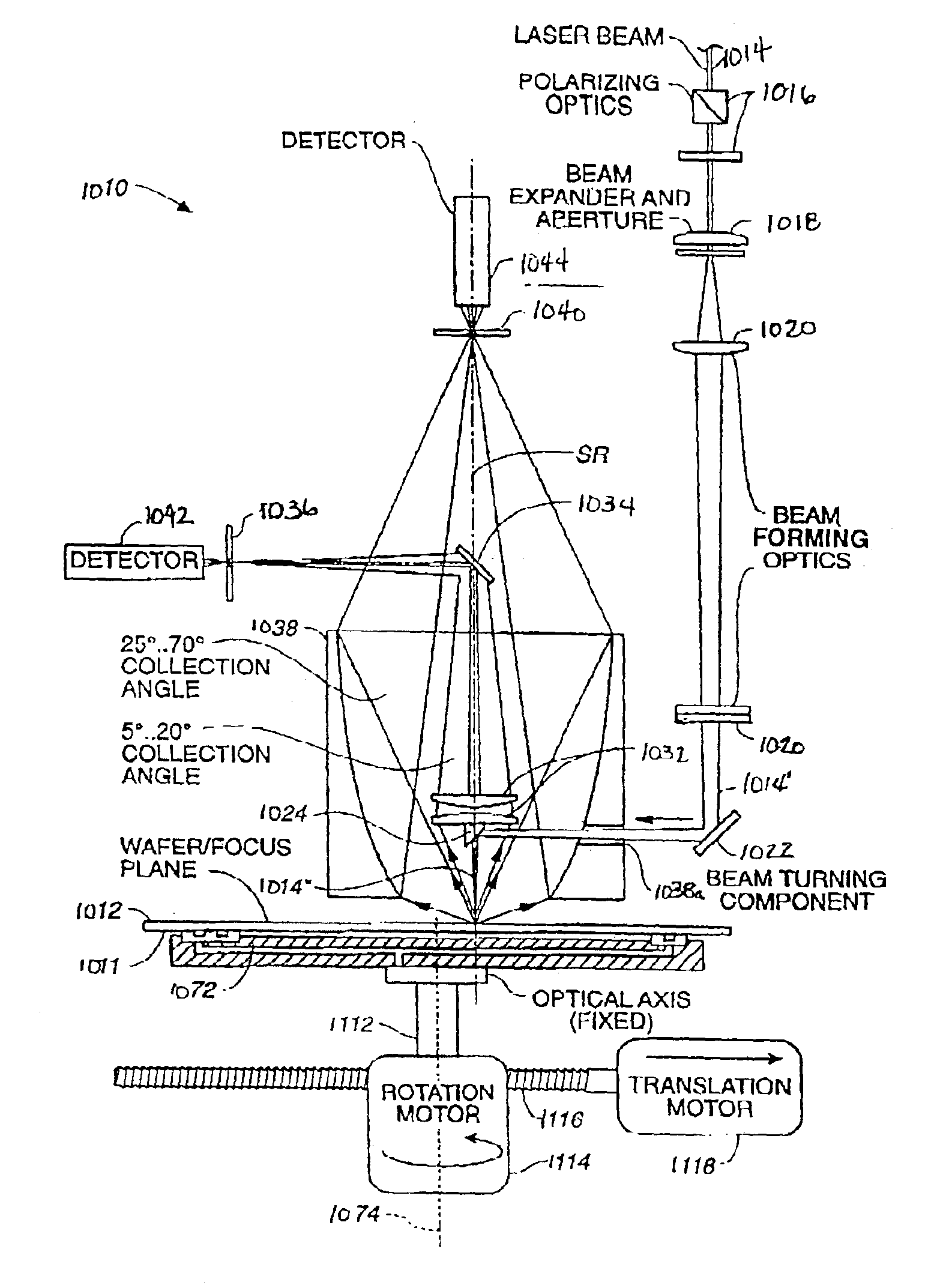
[0051]The purpose of the present invention is, therefore, to propose a method and an assembly that avoids the drawbacks of prior art as described above and whose measuring sensitivity for particles and defects on test objects subjected to inspection is substantially greater, but without limiting haze sensitivity. At the same time, it should provide simple means to permit the adjustment of the sensitivity of the assembly, the size of the illuminated spot on the test object, and thus of the amount of diffused light generated by point defects. In addition, it should make available as large an unmodified portion of the diffused light as possible, to provide a flexible means of selectively separating and further processing the relevant parts of the diffused light, to suit the particular inspection task at hand.

[0052]The present disclosure achieves these aims by the characteristic features described below which provide the main advantages of the invention, namely:[0053]the spatially stati...


PUM


Abstract

A light beam is directed towards a surface along a direction normal to the surface. The surface is caused to move so that the beam scans the surface along a spiral path. An ellipsoidal mirror is placed with its axis along the surface normal to collect light scattered by the surface and any anomalies at the surface at collection angles away from the surface normal. In some applications, a lens arrangement with its axis along the surface normal is also used to collect the light scattered by the surface and any anomalies. The light scattered by the mirror and lenses may be directed to the same or different detectors. Preferably light scattered by the surface within a first range of collection angles from the axis is detected by a first detector and light scattered by the surface within a second range of collection angles from the axis is detected by a second detector. The two ranges of collection angles are different, with one detector optimized to detect scattering from large particles and defects and the other detector optimized to detect light from small particles and defects.

Description

CROSS-REFERENCE TO RELATED APPLICATIONS[0001]The present application is a continuation of U.S. patent application Ser. No. 09 / 901,998 filed on Jul. 10, 2001, now U.S. Pat. No. 6,606,153, which is a continuation application of U.S. patent application Ser. No. 08 / 770,491, filed Dec. 20, 1996, now U.S. Pat. No. 6,271,916, which is a continuation-in-part application of U.S. patent application Ser. No. 08 / 216,834, filed Mar. 24, 1994, now abandoned, and of U.S. patent application Ser. No. 08 / 533,632, filed Sep. 25, 1995, now abandoned.BACKGROUND OF THE INVENTION[0002]The invention described in the present disclosure relates to a process and an assembly for the non-destructive inspection of surfaces, particularly for the measurement of small particles, defects, and inhomogeneities on and / or just below the surface of a test object, such particles, defects, and inhomogeneities collectively referred to herein as anomalies. It relates in particular to an instrument described below as the pref...

Claims


Application Information

Patent Timeline
IPC IPC(8): G01N21/88G01N21/94G01N21/95
CPCG01N21/94G01N21/9501
Inventor MARXER, NORBERTGROSS, KENNETH P.ALTENDORFER, HUBERTKREN, GEORGE
Owner KLA TENCOR CORP
Why Eureka
Try Eureka