Endless belt device and image forming apparatus using the device

Active Publication Date: 2006-05-18
RICOH KK
View PDF3 Cites 5 Cited by
  • Summary
  • Abstract
  • Description
  • Claims
  • Application Information

AI Technical Summary

Benefits of technology

[0015] Preferred embodiments of the present invention provide a novel endless belt device with an endless belt that can accomplish reducing the size of a detection device detecting the speed of the endless belt and enhancing the detection accuracy of the detection device and that can decrease an electrostatic effect by the detection device relative to the surface of the endless belt, and a novel image forming apparatus using the endless belt device.
[0016] The preferred embodiments of the present invention further provide a novel endless belt device with an endless belt that can maintain satisfactory detection accuracy of a detection device detecting the speed of the endless belt, for a long term, and a novel image forming apparatus using the endless belt device.
[0018] Thus, in the endless belt device, a separate member (e.g., an encoder) for forming a marker is not required within the rotation surface of the endless belt, and the reflection-type sensor as a detection member is arranged only at one side of the circumferential surface of the rotation axis, so that reducing the size of the detection mechanism is realized. Further, because the marker is not formed on the endless belt, the electrostatic effect to the surface of the endless belt is decreased.
[0020] Thereby, the reflection-type sensor and the marker are positioned with high accuracy, so that enhancing the detection accuracy is realized.
[0022] Thereby, an erroneous operation of the reflection-type sensor, which may be caused by toner and / or dust adhering to the reflection-type sensor and / or the marker or a light invaded from outside, is avoided.

Problems solved by technology

In the speed detection method using an encoder disk, however, a detection mechanism protrudes from an end part of a rotation axis, and a disk with an axis having a diameter larger than that of the rotation axis is necessary for the detection mechanism, so that the detection mechanism is relatively large.
In the method of using a transmittance-type sensor at a D-shaped part of an end part of an axis, the detection mechanism is relatively large, similarly, and further, it is difficult to arbitrarily set the number of markers, so that adjustment of the detection accuracy is difficult.
In the method of providing a marker on a photoconductor drum in the circumferential direction thereof and detecting the marker by a photo-interrupter, the photo-interrupter cannot be close to the photoconductor drum due to a concern that the photoconductive property of the photoconductor drum is affected, so that the detection accuracy cannot be increased so much.
Further, there is a concern that the charged marker electrostatically affects the surface of an endless belt arranged close to the photoconductor drum.

Method used


Image

  • Endless belt device and image forming apparatus using the device
  • Endless belt device and image forming apparatus using the device
  • Endless belt device and image forming apparatus using the device

Examples


Embodiment Construction

[0039] Referring now to the drawings, wherein like reference numerals designate identical or corresponding parts throughout the several views, preferred embodiments of the present invention are described.

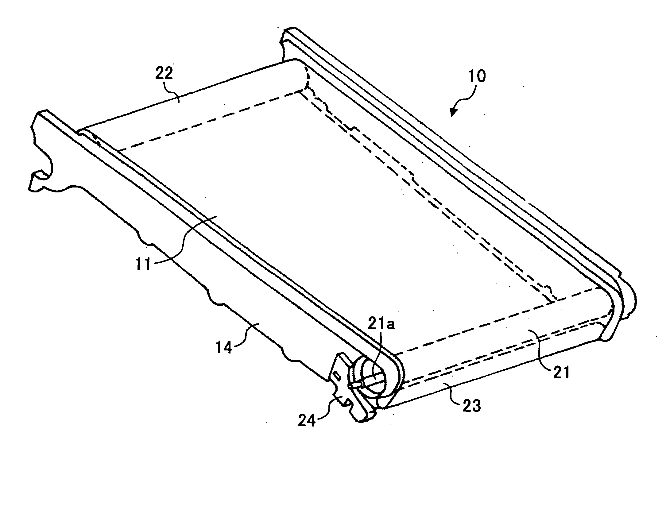
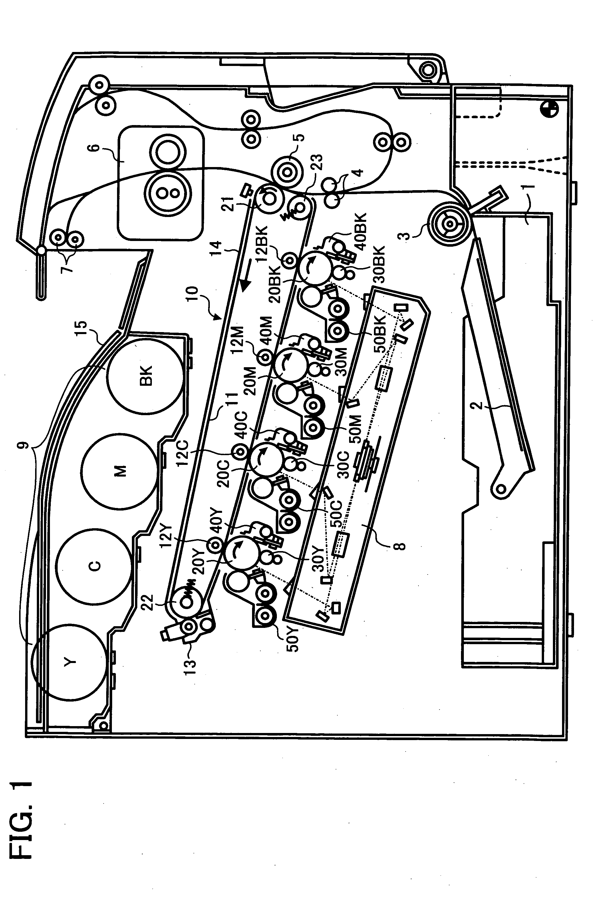
[0040]FIG. 1 is a diagram schematically illustrating the construction of a color printer as an image forming apparatus according to an embodiment of the present invention. A transfer belt unit 10 as an endless belt device of the present invention, having an intermediary transfer belt 11 as an endless belt, and four image formation stations are arranged at the center part of the apparatus main body.

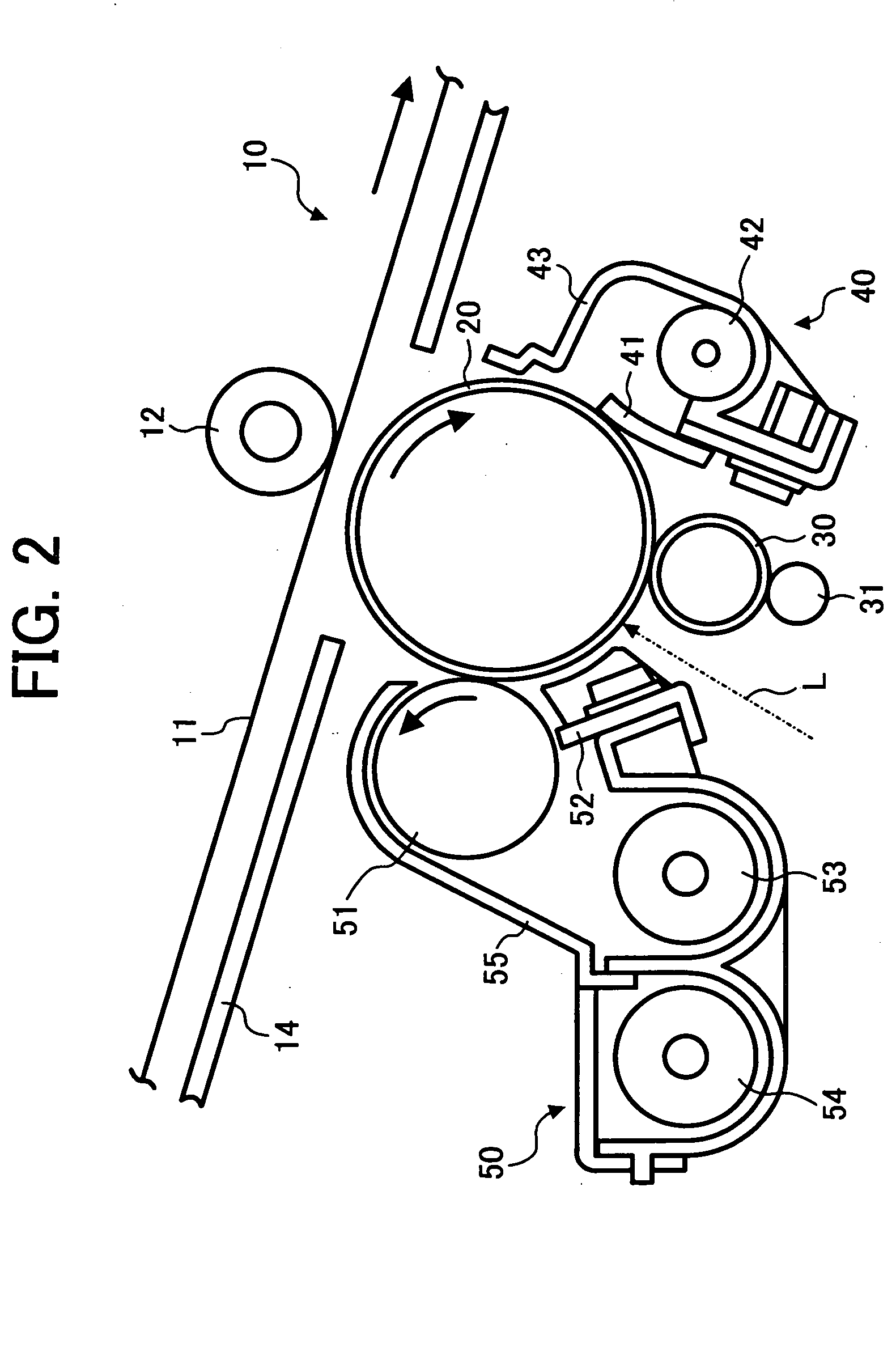
[0041] The image formation stations include photoconductor drums 20Y, 20C, 20M, and 20BK, respectively, and charging devices 30Y, 30C, 30M, and 30BK, development devices 50Y, 50C, 50M, and 50BK, and cleaning devices 40Y, 40C, 40M, and 40BK are arranged around the photoconductor drums 20Y, 20C, 20M and 20BK, respectively.

[0042] A toner bottle group 9 for replenishing toner is arranged at...


PUM


Abstract

An endless belt device includes an endless belt and a plurality of rotary members rotatably supporting the endless belt. One of the plurality of rotary members includes a marker formed on a part of a circumferential surface of a rotation axis thereof. A reflection-type sensor is arranged to oppose the circumferential surface of the rotation axis of the one of the plurality of rotary members to detect the marker formed on the circumferential surface. A rotation speed of the endless belt is detected by detecting the marker on the circumferential surface of the rotation axis of the one of the plurality of rotary members by the reflection-type sensor.

Description

BACKGROUND OF THE INVENTION [0001] 1. Field of the Invention [0002] The present invention relates to an endless belt device provided with an endless belt for bearing an image or a medium for forming an image or for pressing the medium, and an image forming apparatus using the endless belt device, such as a copier, a printer, a facsimile apparatus, etc. [0003] 2. Discussion of the Background [0004] A tandem-type color image forming apparatus in which a plurality of photoconductors as image bearing members are arranged side-by-side obtains a full color image on a recording medium by transferring toner images formed on respective photoconductors onto an endless belt as an intermediary transfer member, sequentially, to be superimposed on top of each other and by transferring the superimposed toner images onto the recording medium in a lump. [0005] In the image forming apparatus, the toner images formed on the plurality of photoconductors are transferred onto the intermediary transfer me...

Claims


Application Information

Patent Timeline
IPC IPC(8): G03G15/01
CPCG03G15/0131G03G2215/0119G03G2215/0158
Inventor SAITO, DAISUKETAKEICHI, RYUTAFURUYA, MASAHARUNAKAYAMA, TAKAHIRO
Owner RICOH KK
Why Eureka
Try Eureka