Enhanced Sensitivity Line Field Detection

Inactive Publication Date: 2013-09-05
PHYSICAL SCI
View PDF3 Cites 8 Cited by
  • Summary
  • Abstract
  • Description
  • Claims
  • Application Information

AI Technical Summary

Benefits of technology

The invention is about improving the detection of signals from the eye, specifically using different types of detectors and techniques to increase sensitivity. The detection device can be incorporated into a line scanning ophthalmoscope platform, and multiple image modalities can be combined for enhanced retinal disease visualization and treatment. The method involves scanning a line of light along a portion of the retina, descan reflected light, and provide output light in a line focus configuration while detecting a signal associated with an image of the portion of the retina scanned using multiple linear arrays of pixels. The synchronization of scanning and exposure on the multiple linear arrays of pixels can increase exposure time for each spatial region of the retina scanned. The apparatus can also include means for tracking a reference feature of the retina and controlling the position of the line of light relative to the reference feature to correct for motion of the eye.

Problems solved by technology

While digital flash fundus photography is the clinical standard for angiography, it is difficult to configure for continuous imaging (e.g., video imaging) to visualize the entire sequence of dye infusion from early phase transit to late phase pooling.
Because fluorescent signal is already confined to the retinal and choroidal vasculature, the depth sectioning capability of SLO's is less advantageous for exogenous dye angiography.
Because of the fixed pixel size, the light collection properties cannot be controlled as easily as an SLO, which can be configured with adjustable or different-sized pinholes.
Existing LSA techniques do not collect extremely low light levels to enhance LSA for AF, FA, and ICGA.

Method used


Image

  • Enhanced Sensitivity Line Field Detection
  • Enhanced Sensitivity Line Field Detection
  • Enhanced Sensitivity Line Field Detection

Examples


Embodiment Construction

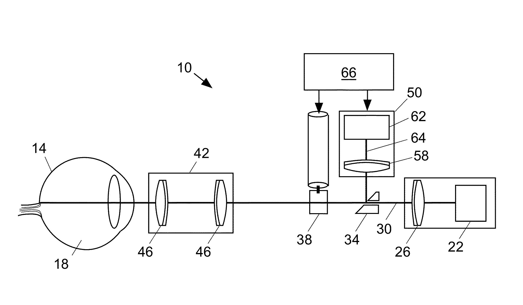
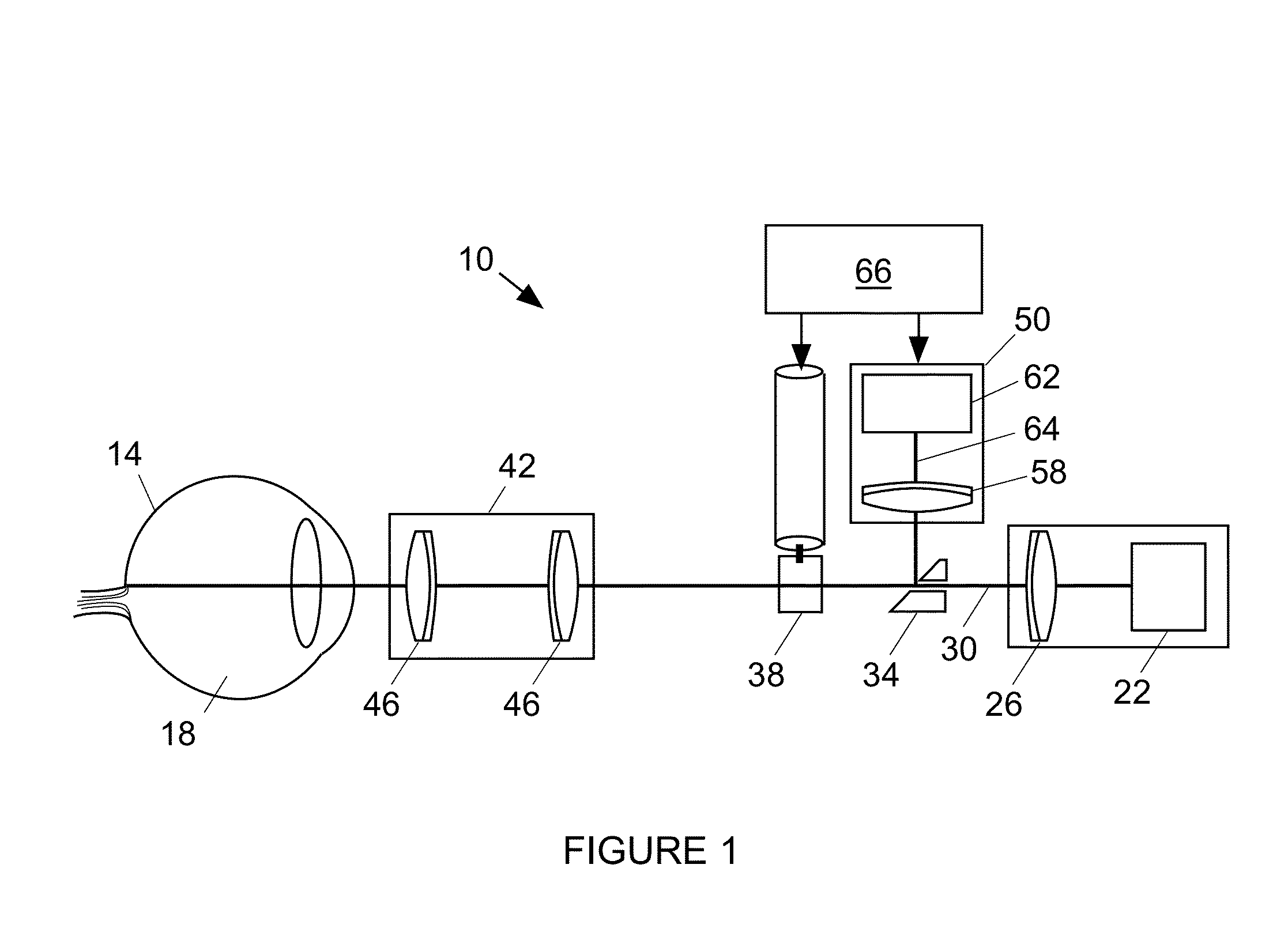
[0040]FIG. 1 shows an illustrative embodiment of a retinal imaging device 10 including and an optical system configured to (i) scan a portion of a retina 14 of an eye 18 with a line of light, (ii) descan reflected light from the scanned portion of the retina, and (iii) provide output light in a line focus configuration. The optical system can be a line scan ophthalmoscope (LSO), e.g., a line scan laser ophthalmoscope (LSLO) or a LSO using a diode or superluminescent diode (SLD). The optical system can provide an image having a wide field of view.

[0041]The optical system includes a source 22 and a lens system 26 to form the input beam 30 into a line of light. The optical system includes a beam separator 34 including an aperture through which the line of light passes and includes a galvanometer 38 to control the position of the imaging beam. The optical system includes an ocular interface 42 including one or more ophthalmic lens 46 for focusing the line of light in the retina.

[0042]Li...


PUM


Abstract

A retinal imaging device includes an optical system configured to (i) scan a portion of the retina of the eye with a line of light, (ii) descan reflected light from the scanned portion of the retina, and (iii) provide output light in a line focus configuration. The device includes a detection device including a linear array of asymmetric pixels having at least a 2:1 ratio of length to width, a detection device with multiple adjacent linear arrays, and / or a detection device using a time delay and integration (TDI) architecture.

Description

GOVERNMENT RIGHTS[0001]The invention was made with government support under Department of Defense contract no. W81XWH-06-C-0397. The government has certain rights in the invention.FIELD OF THE INVENTION[0002]The invention relates generally to enhanced line field retinal imaging, and more particularly, to a line scanning ophthalmoscope incorporating a detection device with asymmetric pixels, a detection device with multiple adjacent linear arrays, and / or a detection device using a time delay and integration (TDI) architecture.BACKGROUND[0003]In vivo ophthalmic images are produced by back-reflected light from ocular tissue (e.g., retina, cornea, lens, etc.) and can overcome the problem of weak signals for applications such as detection of exogenous and endogenous fluorescence, molecular signatures, high-speed dynamics, multiphoton imaging, and others. In general, fundus imaging can be divided into three major device categories: flood illumination, line scanning or line field, and conf...

Claims


Application Information

Patent Timeline
IPC IPC(8): A61B3/14
CPCA61B3/1025
Inventor HAMMER, DANIEL X.FERGUSON, R. DANIELMUJAT, MIRCEAIFTIMIA, NICUSOR V.
Owner PHYSICAL SCI
Why Eureka
Try Eureka