Spectral sensors

Pending Publication Date: 2021-08-19
INTERUNIVERSITAIR MICRO ELECTRONICS CENT (IMEC VZW)
View PDF2 Cites 0 Cited by
  • Summary
  • Abstract
  • Description
  • Claims
  • Application Information

AI Technical Summary

Benefits of technology

[0025]In view of the above discussion in connection with the first aspect, it may be appreciated that an advantage of the third aspect is that an image sensor capable of spectral imaging having an enhanced sensitivity and s

Problems solved by technology

However, due to their spectral selectivity, the filters inherently reduce the amount

Method used


Image

  • Spectral sensors
  • Spectral sensors

Examples


Embodiment Construction

[0034]The present inventive concept will now be described with reference to the accompanying drawings, in which currently preferred variants of the inventive concept are shown. This inventive concept may, however, be implemented in many different forms and should not be construed as limited to the variants set forth herein.

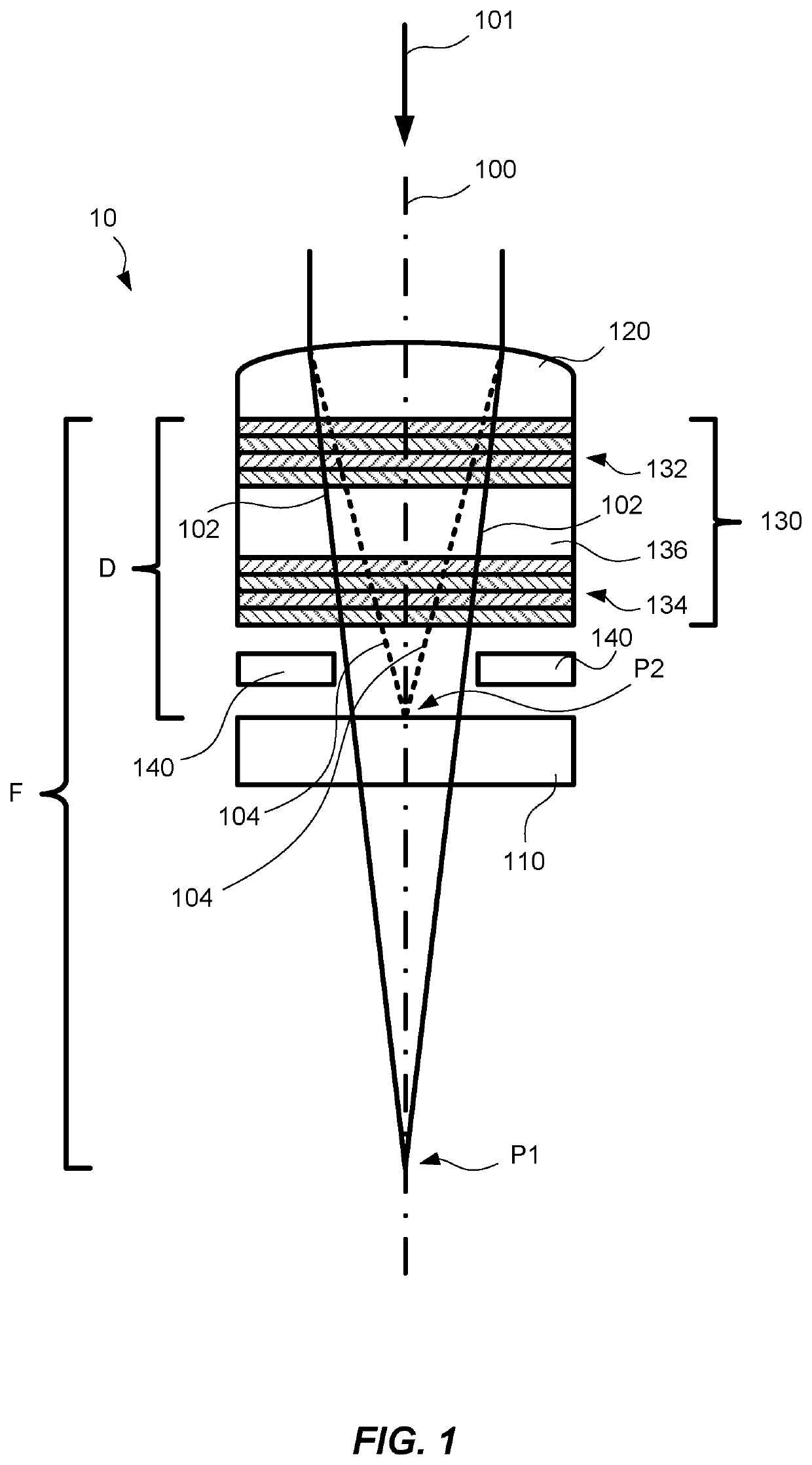
[0035]FIG. 1 illustrates a spectral sensor 10. The spectral sensor 10 comprises a light detecting element 110, a microlens 120, and an interference filter 130. The spectral sensor 10 may further comprise circuitry for conveying control signals, read-out signals etc. to / from the pixel, as schematically represented by metal layer 140 in FIG. 1. An optical axis 100 of the spectral sensor 10 is further illustrated in FIG. 1. The optical axis 100 may be parallel to a normal (not shown in FIG. 1) of the interference filter 130, as is the case in the example of FIG. 1. A general direction of light incident on the spectral sensor 10 is represented by arrow 101 in FIG. 1.

[...


PUM


Abstract

The present invention relates to a spectral sensor. The spectral sensor comprising: a light detecting element; a microlens; and an interference filter arranged between the light detecting element and the microlens, and configured to transmit light in one or more spectral bands; wherein the microlens has an effective focal length (F) exceeding a distance (D) between the microlens and the light detecting element. The microlens may be configured such that light refracted by the microlens, to be transmitted through the interference filter, converges towards a position (P) behind the light detecting element. The present invention further relates to an image sensor comprising a plurality of spectral sensors.

Description

CROSS REFERENCE TO RELATED APPLICATIONS[0001]This application claims priority to the European Patent Application EPC, No. 20157949.7, filed on Feb. 18, 2020, which is incorporated herein by reference.TECHNICAL FIELD[0002]The present invention relates to spectral sensors and an image sensor comprising a plurality of spectral sensors.BACKGROUND OF THE INVENTION[0003]There are many applications in which it is desirable to acquire spectral images of an object. In this type of imaging, spectral information of an object is detected in multiple narrow ranges of wavelengths. Two such techniques are called multispectral imaging and hyperspectral imaging, and while no definitions have been established, multispectral imaging typically refers to spectral imaging using a plurality of discrete wavelength bands, whereas hyperspectral imaging refers to imaging narrow spectral wavelength bands over a continuous spectral range. Hyperspectral imaging may also often use a larger number of spectral band...

Claims


Application Information

Patent Timeline
IPC IPC(8): H01L27/146
CPCH01L27/14621H01L27/14643H01L27/14627H01L31/02165G01J3/2803G01J3/12G01J2003/1213G01J3/0208G01J1/0411G01J1/0488G01J1/4228G01J1/42G01J3/0259G01J3/26H01L31/02327H01L31/103H01L31/105
Inventor SPOOREN, NICKGEELEN, BERT
Owner INTERUNIVERSITAIR MICRO ELECTRONICS CENT (IMEC VZW)
Why Eureka
Try Eureka