Image forming device, a method of controlling image forming device, and a computer program product for controlling image forming device and providing location information

a technology of image forming device and computer program product, which is applied in the direction of visual presentation using printers, digital output to print units, instruments, etc., can solve the problems of user difficulty in finding the transfer destination, the difficulty of determining the page location of the transferred page, and the difficulty of determining the transfer date. the effect of user burden, easy to advise the user

Inactive Publication Date: 2005-06-14
MINOLTA CO LTD
View PDF7 Cites 12 Cited by
  • Summary
  • Abstract
  • Description
  • Claims
  • Application Information

AI Technical Summary

Benefits of technology

[0009]It is an object of this invention to provide an image forming device, its control method and a computer program product that can eliminate the user's burden of memorizing or writing down the transfe

Problems solved by technology

Also,if the system only notifies the computer that requested the print about the transfer location, the user may have difficulty finding the transfer destination as the printer may automatically separate the print and divert a portion of the print job to another printer after the user left the computer to pick up the print at the originally specified printer.
Moreover, if a print job is divided and a

Method used


Image

  • Image forming device, a method of controlling image forming device, and a computer program product for controlling image forming device and providing location information
  • Image forming device, a method of controlling image forming device, and a computer program product for controlling image forming device and providing location information
  • Image forming device, a method of controlling image forming device, and a computer program product for controlling image forming device and providing location information

Examples


first embodiment

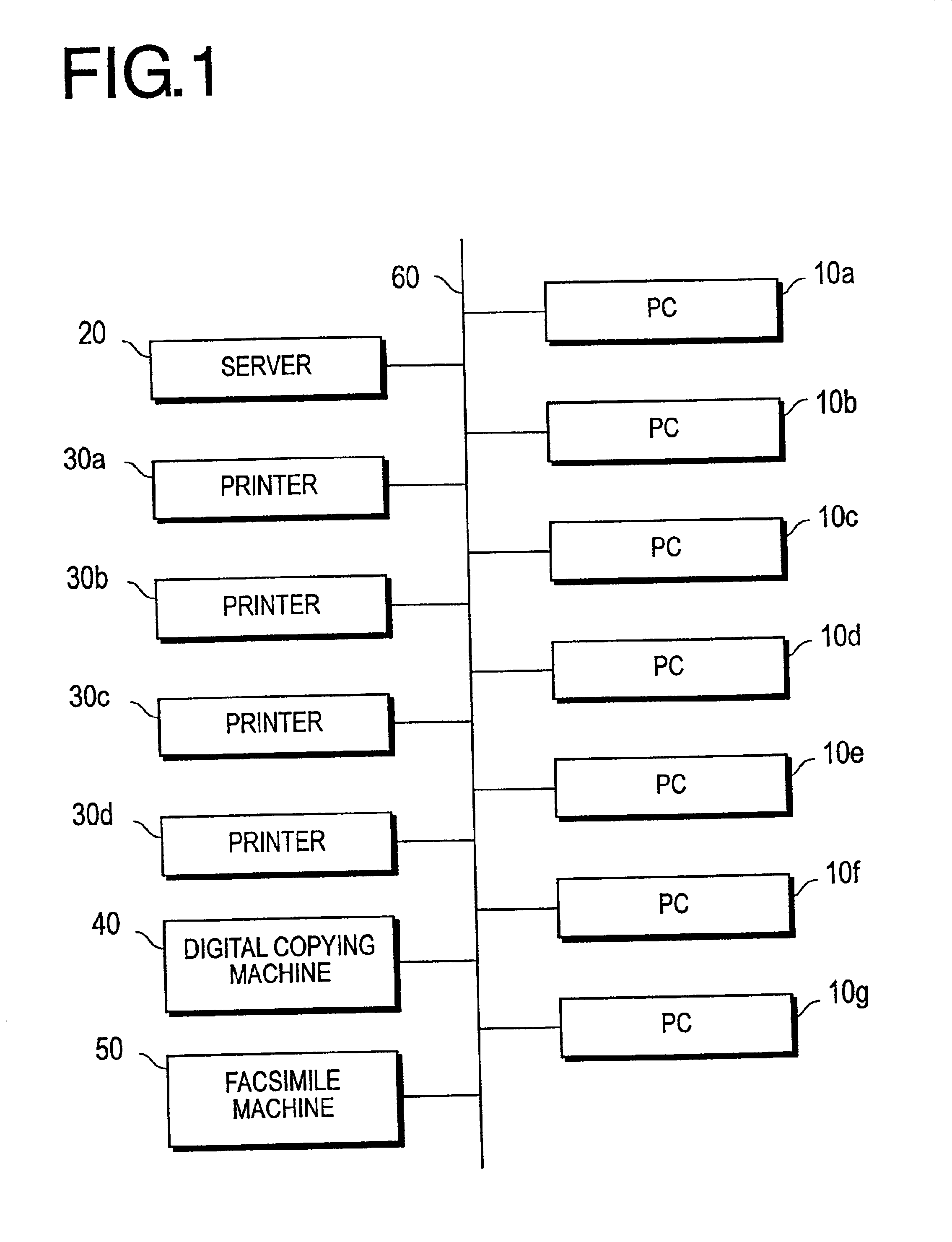
[0046]FIG. 1 shows an example constitution of a network system, which is a preferred embodiment of this invention.

[0047]In this network system, personal computers (“PC”) 10a-10g, a server 20, printers 30a-30d, a digital copying machine 40, and a facsimile machine 50 are interconnected via a network 60. The network 60 is constituted of a LAN such as Ethernet. The types and quantities of computers and peripheral equipment connected to the network 60 are not limited to those shown in FIG. 1. For example, in place of or in addition to a PC, a workstation can be connected to the network 60. Also, a scanner can be connected to the network 60 as a piece of peripheral equipment.

[0048]Any one of PCs or printers used in this system will be denoted in the following by their reference numbers 10 and 30 respectively.

[0049]The PC 10 prepares a print job and transmits it to an arbitrary printer 30. Application software and printer driver software are installed on the PC 10. The application softwar...

second embodiment

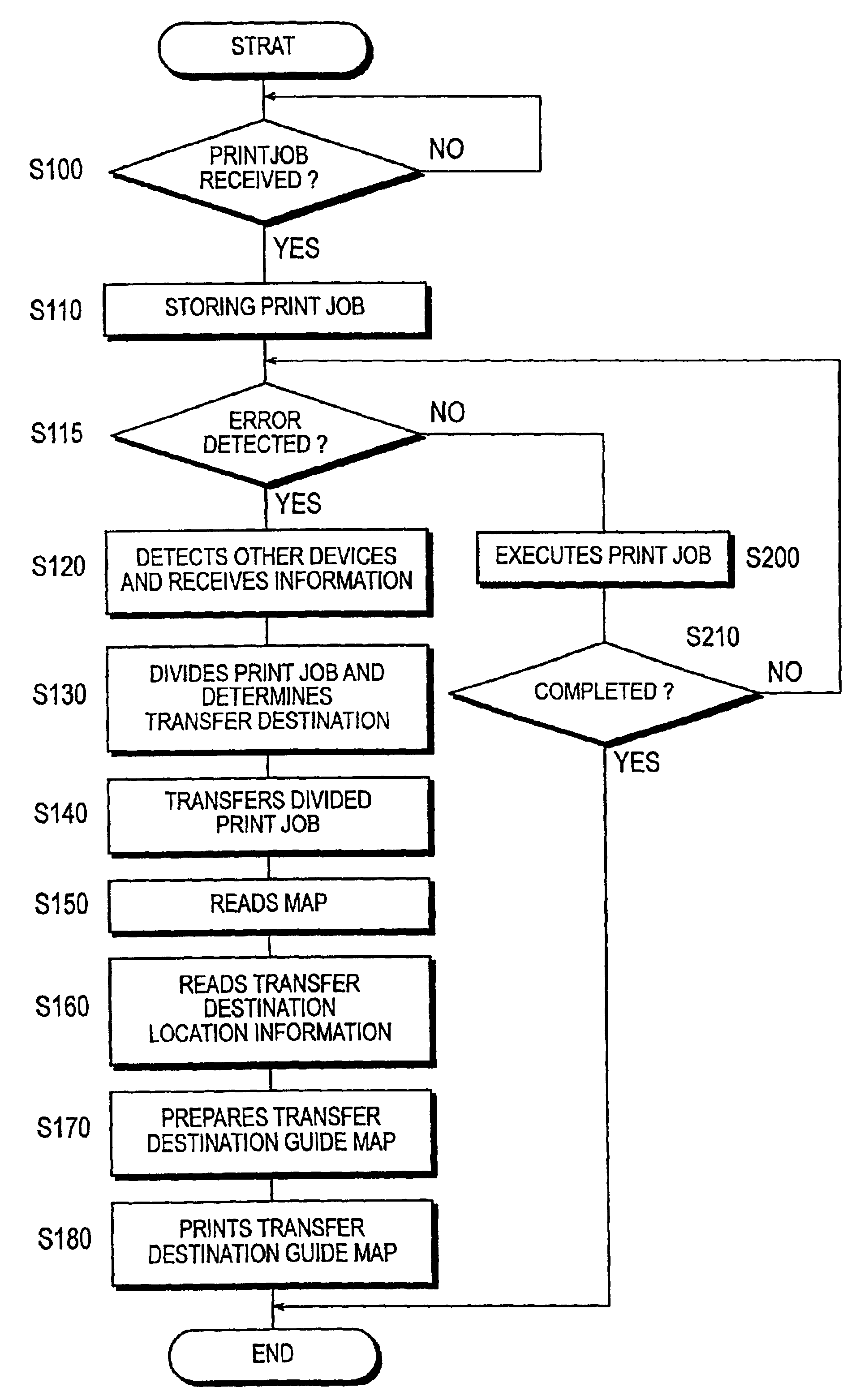
[0091]The second embodiment is a case where printing is executed without interruption by dividing the print job and printing it by other printers when a minor error occurs at the specified device such as a shortage of paper of the particular size or paper jam.

[0092]It is described that the user is specifying the printer 30a for the sake of simplicity.

[0093]FIG. 8 is a flowchart showing the operation of the printer 30a that corresponds to the second embodiment. Specifically, FIG. 8 shows the operation of the printer 30a when it receives a print job from the PC 10. The algorithm shown in the flowchart of FIG. 8 is stored as a control program in the ROM 32 of the printer 30 and is executed by the CPU 31. The drawing used here is the same as the one used in the first embodiment unless otherwise indicated specifically.

[0094]Since the steps S100 and S110 are identical to those in the flowchart shown in FIG. 3, their descriptions are not repeated here.

[0095]At the step S115, a judgment is ...

third embodiment

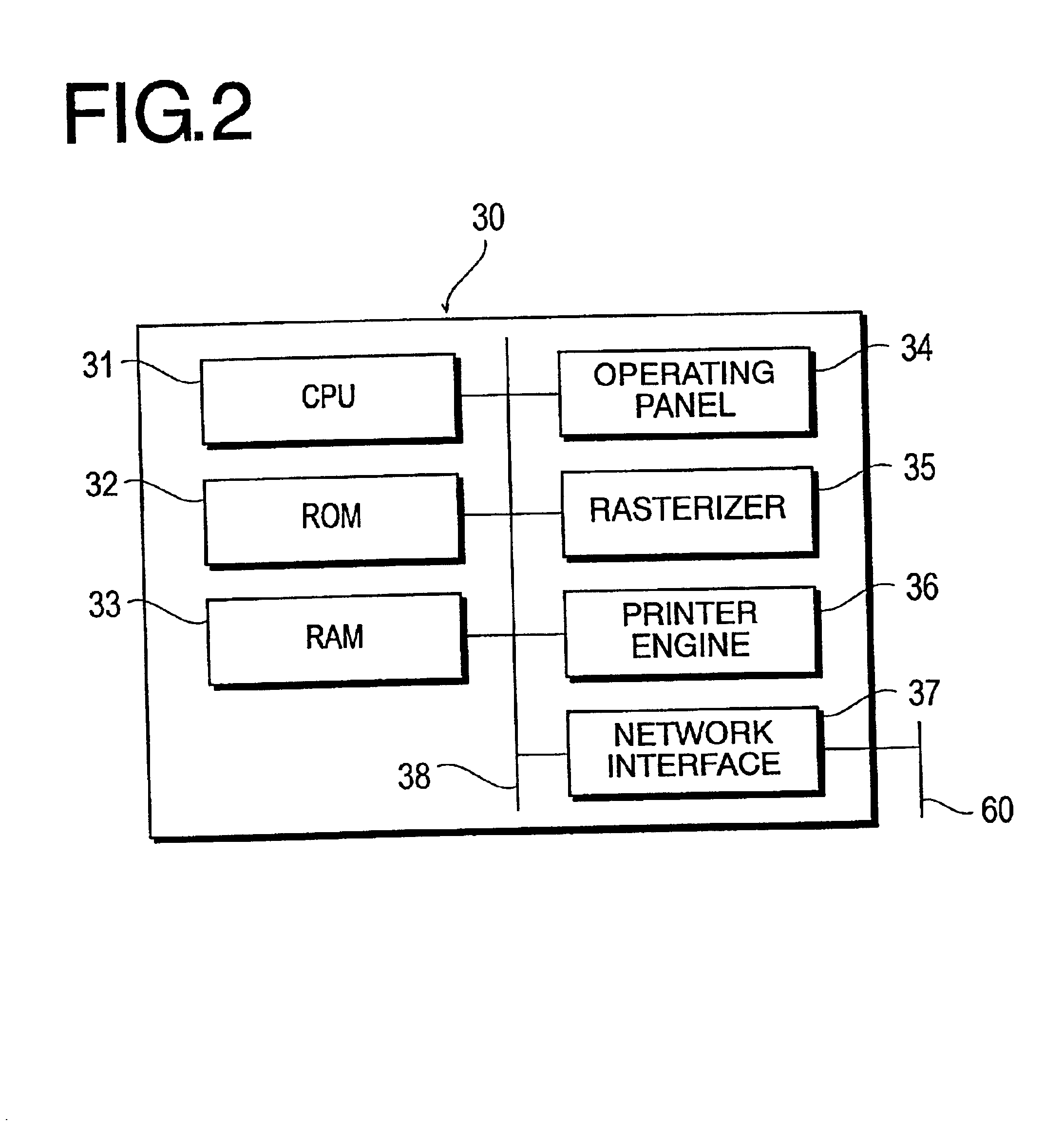
[0101]The third embodiment shows a case where the transfer destination location information is insert printed instead of the transferred page. In this embodiment, the transfer destination guide map added with the transfer destination's location information is insertion-printed. The contents of the insertion printing will be described later. Since the constitution of the network system in this embodiment including the PC 10a-10g, printer 30a-30d, digital copying machine 40 and facsimile machine 50 is identical to that shown in FIG. 1 and FIG. 2 in the first embodiment, the detail descriptions are not repeated here. Identical members are identified using the same reference codes.

[0102]For the sake of the simplicity, it is described that the PC 10 specifies the printer 30a, and the printer 30a transfers a portion of the print job it received to the printers 30b and 30c.

[0103]FIG. 9 is a diagram for describing the contents of the process in a case corresponding to the third embodiment,...


PUM


Abstract

A printer 30a that was originally specified by the user Prints a transfer destination guide map, on which the location information of other printers is shown, when a portion or all of a print job is transferred to those other printers. The transfer destination guide map is further added with information useful for the user such as the expected time of completion for the print out, the number of printed sheets, and the route of pick up. The transfer destination guide map is insert-printed on the page position of the transferred page.

Description

[0001]This application is based on Japanese Patent Application Nos. 2000-155324 and 2000-164891 filed on May 25, 2000 and Jun. 1, 2000 respectively, the contents of which are hereby incorporated by reference.BACKGROUND OF THE INVENTION[0002]1. Field of the Invention[0003]The present invention relates to an image forming device, a method of controlling an image forming device and a computer program product for controlling an image forming device.[0004]2. Description of Related Art[0005]As the scale of computer networks becomes larger, a type of network system is becoming popular in which multiple image forming devices such as printers and digital copying machines (descriptions of the invention will be made hereinafter using a printer as an example) are interconnected with each other through the network. In such a network system, a technology is known in which a portion of or all of the print jobs assigned to a printer are transferred to other printers. For example, a printer that rec...

Claims


Application Information

Patent Timeline
IPC IPC(8): G06F3/12
CPCG06F3/1204G06F3/1288G06F3/1241G06F3/1261G06F3/1213G06F3/1207
Inventor KATSUDA, TAKEOIDEHARA, TAKENORI
Owner MINOLTA CO LTD
Why Eureka
Try Eureka