
Optical disc driver enclosure

a technology of optical disc drives and enclosures, which is applied in the installation of lighting conductors, electrical apparatus casings/cabinets/drawers, and coupling device connections, etc., can solve the problems of difficult to disengage the second cover from the first cover, damage to the optical disc drive in the enclosure, and the two covers are difficult to properly align before engaging one, etc., to achieve the effect of convenient assembly and disassembly

Inactive Publication Date: 2005-06-21
HON HAI PRECISION IND CO LTD
View PDF8 Cites 37 Cited by
  • Summary
  • Abstract
  • Description
  • Claims
  • Application Information

AI Technical Summary

Benefits of technology

[0005]Accordingly, an object of the present invention is to provide an optical disc drive enclosure which is easily assembled and disassembled.

Problems solved by technology

However, there are no guiding means on the first or second covers to aid assembly of the two covers, so the two covers are difficult to properly align before engaging one to the other.
Furthermore, once the second cover is engaged improperly to the first cover, it is difficult to disengage the second cover from the first cover.
If too much force is used to disengage the two covers, the elements of the optical disc drive in the covers might be damaged.

Method used


Image

  • Optical disc driver enclosure
  • Optical disc driver enclosure
  • Optical disc driver enclosure

Examples


Embodiment Construction

[0015]Reference will now be made to the drawing figures to describe the preferred embodiments of the present invention in detail.

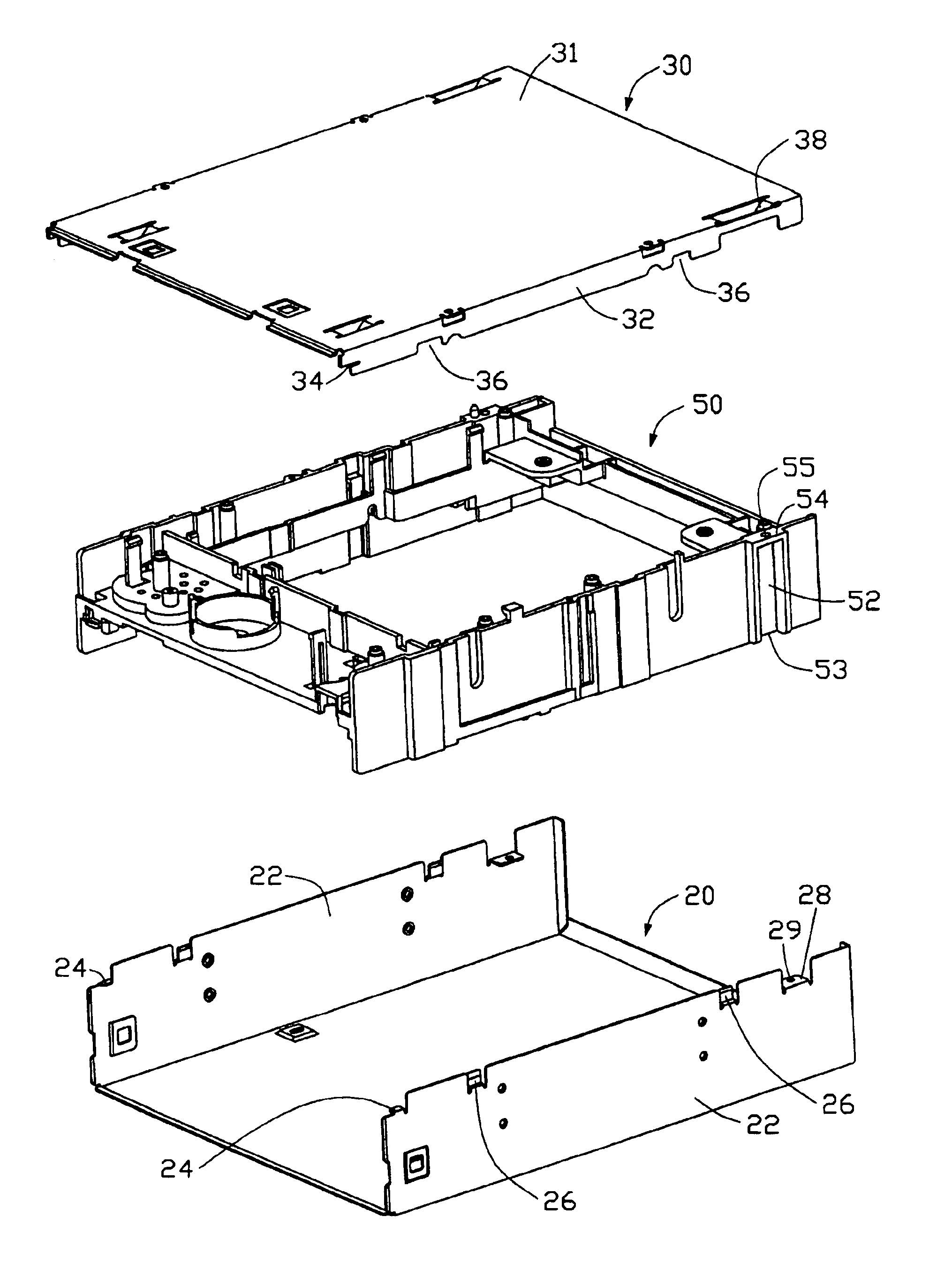
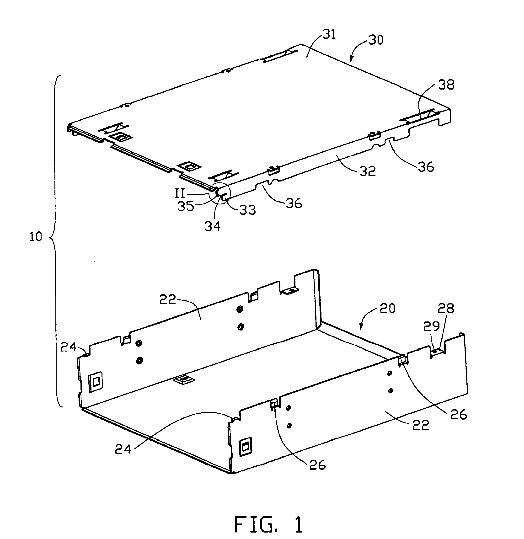
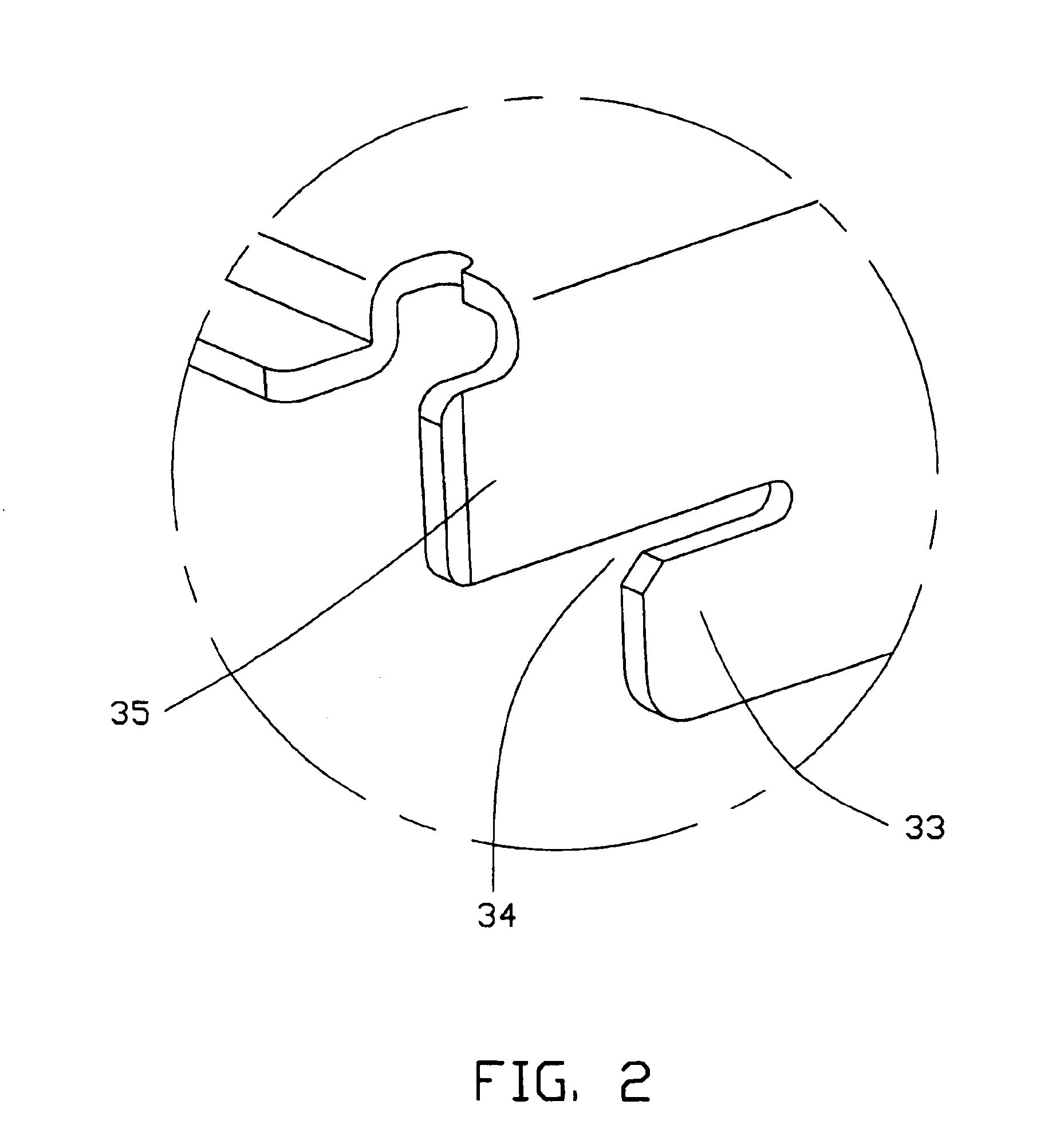
[0016]As shown in FIGS. 1-2, an optical disc drive enclosure 10 in accordance with a first embodiment of the present invention includes a first cover 20 and a second cover 30. The first cover 20 has a bottom plate (not labeled) and two first side plates 22. A locating plate 24 extends inwardly and horizontally from an upper edge near a front of each first side plate 22. At least one protrusion plate 26 is stamped inwardly and upwardly at the upper edge of each first side plate 22. Each protrusion plate 26 is parallel to the first side plate 22, and spaced a certain distance therefrom. A locking plate 28 extends inwardly and horizontally from an upper edge near a rear of each first side plate 22. A threaded hole 29 is defined in the locking plate 28.

[0017]The second cover 30 has two second side plates 32 and a top plate 31. A locating slot 34 is defined in ...


PUM


Abstract

An optical disc drive enclosure (10) includes a first cover (20) and a second cover (30). The first cover has a bottom plate and two first side plates (22). A locating plate (24) extends inwardly from a front upper edge of each first side plate, and two protrusion plates (26) are formed on an upper edge of each first side plate. The second cover has a top plate (31) and two second side plates (32). A locating slot (34) is formed at a front end of each second side plate, and can engage with the corresponding locating plate. Two cutouts (36) are defined in each second side plate. During assembly, the locating slots engage with the locating plates, with the second cover at an angle to the first cover. The second cover is then rotated downwardly so that the cutouts engage with the protrusion plates and the second side plates are clipped between the first side plates and the protrusion plates. The first cover and the second cover can then be fixed together by a pair of screws (59).

Description

BACKGROUND OF THE INVENTION[0001]1. Field of the Invention[0002]The present invention generally relates to an optical disc drive enclosure for mounting a drive housing therein, and more particularly to an enclosure having a first cover and a second cover which can be readily and firmly engaged together to securely mount the drive housing in the enclosure.[0003]2. Description of Related Art[0004]In assembling a typical optical disc drive, a drive housing is secured inside a first cover, then a second cover is mounted on the first cover. A typical example is shown in China Patent No. 95204891.4, wherein the optical disc drive enclosure comprises a first cover and a second cover. Ordinarily, 4 to 6 mounting parts are formed on each side plate of the first cover and the second cover, respectively. These mounting parts engage with each other to combine the first cover and the second cover together. However, there are no guiding means on the first or second covers to aid assembly of the t...

Claims


Application Information

Patent Timeline
IPC IPC(8): G11B33/00H02G3/08H05K5/02G11B33/12
CPCG11B33/124
Inventor ZHANG, XIAO LING
Owner HON HAI PRECISION IND CO LTD
Learn More