Motion control device of vehicle

a technology of motion control device and vehicle, which is applied in the direction of process and machine control, braking system, instruments, etc., can solve the problems of inability to maintain tracing performance satisfactorily, and the vehicle's turning radius becomes greater than the expected turning radius

a technology of motion control device and vehicle, which is applied in the direction of process and machine control, braking system, instruments, etc., can solve the problems of inability to maintain tracing performance satisfactorily, and the vehicle's turning radius becomes greater than the expected turning radius

US6910746B2Inactive Publication Date: 2005-06-28ADVICS CO LTD +1

Image

  • Motion control device of vehicle
  • Motion control device of vehicle
  • Motion control device of vehicle

Examples


Embodiment Construction

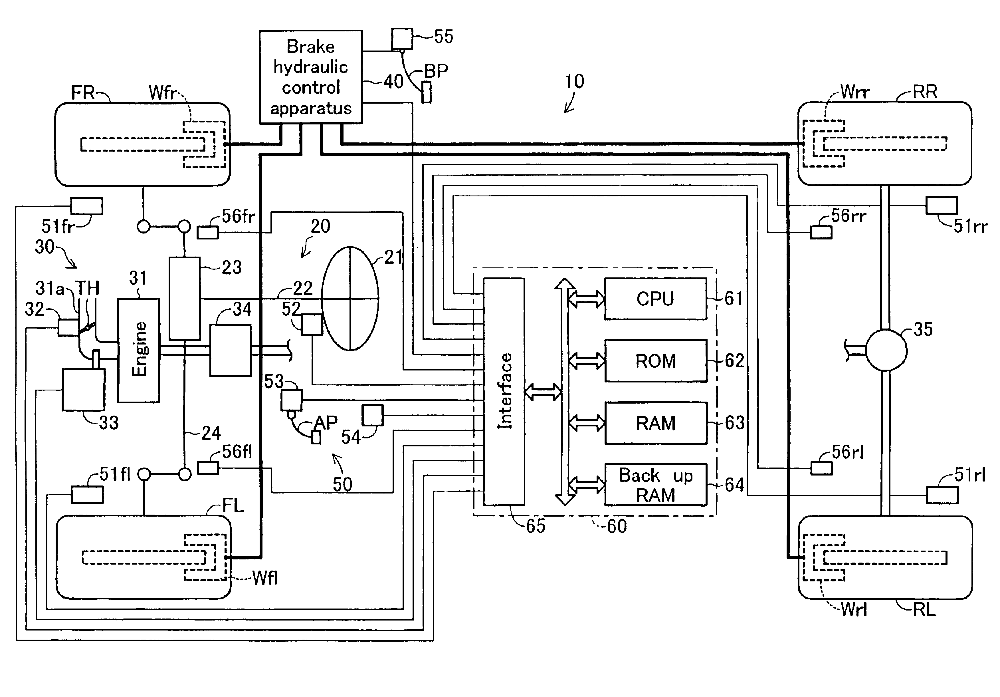
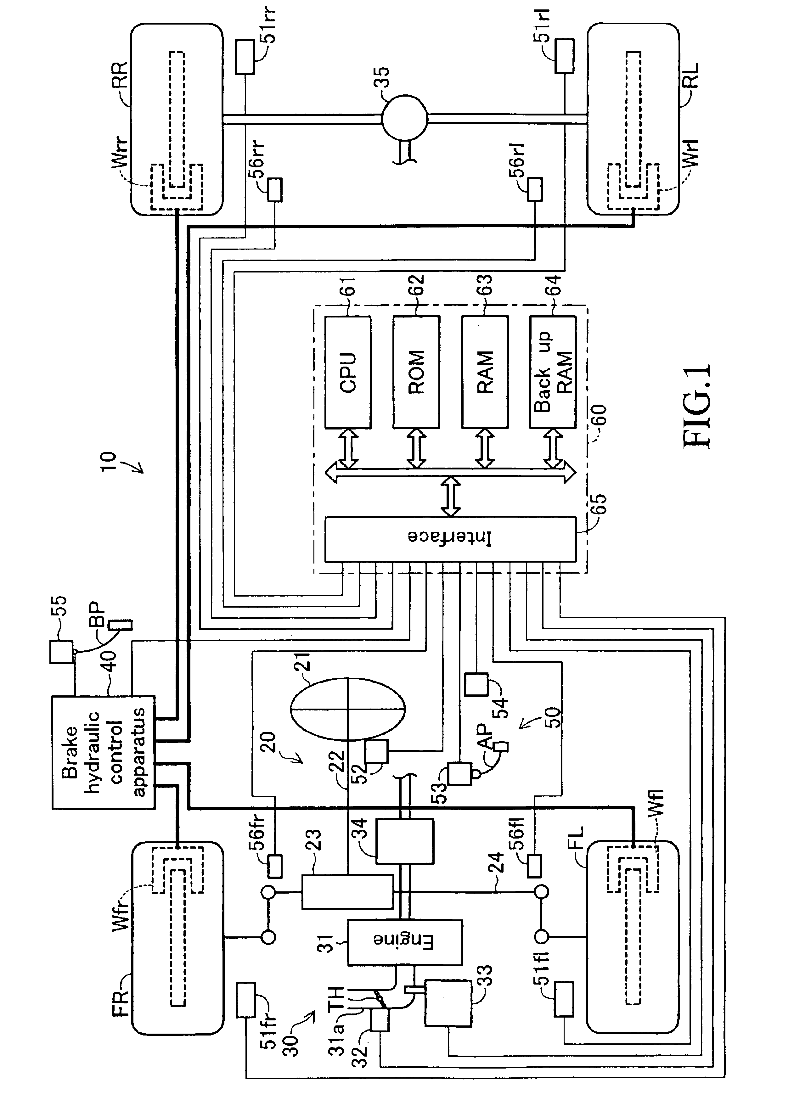
[0027]A preferred embodiment of a motion control device for a vehicle according to the present invention will be explained hereinbelow with reference to drawings. FIG. 1 shows a schematic construction of a vehicle provided with a control device 10 for a vehicle according to the embodiment of the invention. This vehicle is a four-wheel drive vehicle using a rear-wheel drive system and having two front wheels (front-left wheel FL and front-right wheel FR) that are steering wheels as well as non-driving wheels and two rear wheels (rear-left wheel RL and rear-right wheel RR) that are driving wheels.

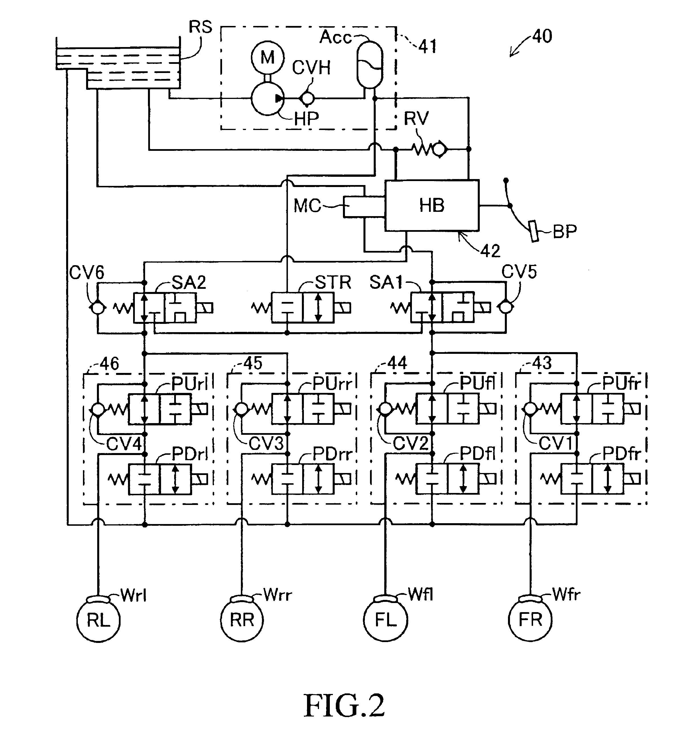
[0028]The control device 10 for the vehicle is configured to include a front-wheel steering mechanism 20 for steering the steering wheels FL and FR, a driving force transmission section 30 that produces driving force and respectively transmits this driving force to each driving wheel RL and RR, a brake hydraulic control apparatus 40 for producing braking force by a brake fluid pressure on eac...


PUM


Abstract

A motion control device 10 for a vehicle exerts braking force only on the rear wheel at the inner side of the turning direction for generating a yawing moment on the vehicle only in the turning direction of the vehicle when an absolute value of an actual lateral acceleration Gy is not more than a value Gyth, i.e., when there is a small possibility of the occurrence of an excessive roll angle on the vehicle body, in case where the turning state of the vehicle is the understeer state. On the other hand, it exerts braking force not only on the rear wheel at the inner side of the turning direction, but also on the front and rear wheels at the outer side of the turning direction for generating a yawing moment in the direction opposite to the turning direction too, when the absolute value of the actual lateral acceleration Gy exceeds the value Gyth, i.e., when there is a great possibility of the occurrence of the excessive roll angle on the vehicle body, in case where the turning state of the vehicle is the understeer state.

Description

BACKGROUND OF THE INVENTION[0001]1. Field of the Invention[0002]The present invention relates to a motion control device for a vehicle for controlling a motion of a vehicle by controlling braking force exerted on each wheel of front wheels and rear wheels of the vehicle.[0003]2. Description of the Prior Arts[0004]There has conventionally been a demand for controlling a motion of a vehicle so as to prevent the turning state of the vehicle from being unstable due to the occurrence of an excessive roll angle on the vehicle upon the turning of the vehicle. This roll angle depends upon the magnitude of an actual lateral acceleration that is a component of an acceleration actually exerted on the vehicle in the side-to-side direction of the vehicle body, and increases with the increase of the actual lateral acceleration. On the other hand, the magnitude of the actual lateral acceleration exerted on the vehicle is decreased by producing a yawing moment in the direction opposite to the turni...

Claims


Application Information

Patent Timeline
28 Jun 2005
Publication
US6910746B2
IPC
B60T8/1766; B60T8/1755; B60T8/24; B60T8/17; B60T8/1764
CPC
B60T8/1766; B60T8/241; B60T8/246; B60T8/17554; B60G2800/0124; B60G2800/215; B60G2800/922; B60T2230/03
Inventors
KATO, TOSHIHISA; FUKAMI, MASANOBU