
Projection-type vehicular headlamp having improved lateral illumination

a projection-type, vehicular headlamp technology, applied in fixed installation, transportation and packaging, light and heating equipment, etc., can solve the problem that the projection-type lamp unit cannot sufficiently illuminate the road zones on and achieve the effect of reliably ensuring visibility to the side of the vehicl

Inactive Publication Date: 2005-06-28
KOITO MFG CO LTD
View PDF8 Cites 41 Cited by
  • Summary
  • Abstract
  • Description
  • Claims
  • Application Information

AI Technical Summary

Benefits of technology

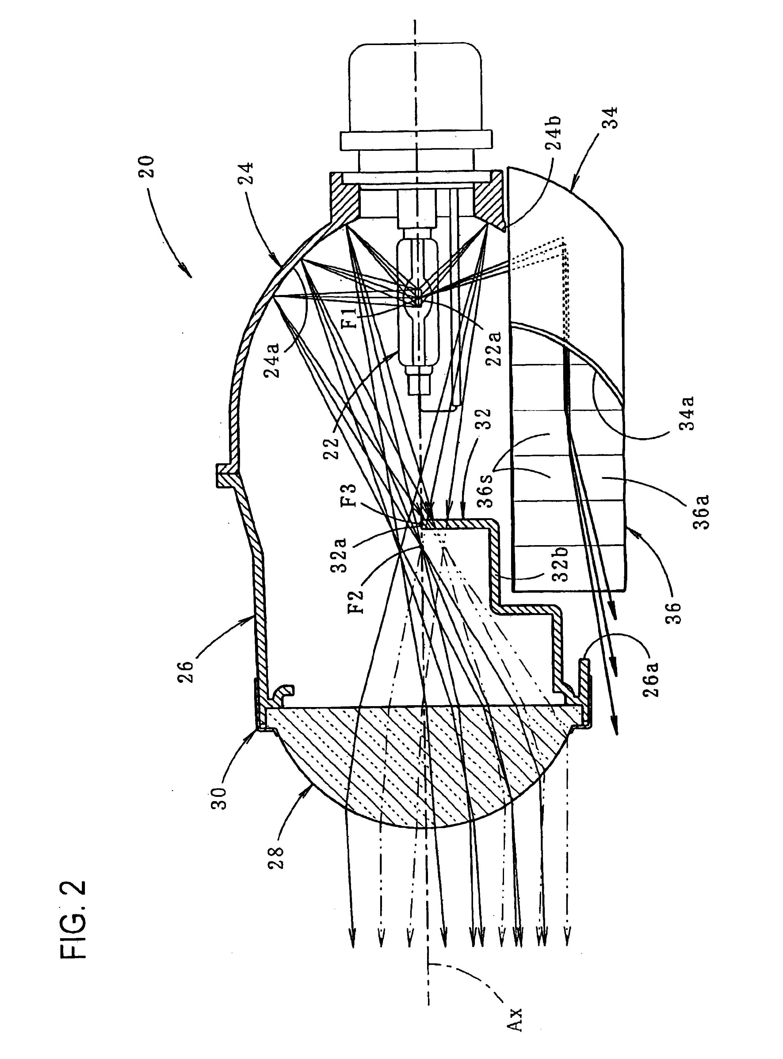
[0014]As described above, the vehicular headlamp according to the present invention is constructed such that a beam is radiated forward in the predetermined low-beam light distribution pattern by the projection-type lamp unit. The first additional reflector for reflecting light from the light source forward is provided below the light source of the lamp unit, and the second additional reflector for reflecting reflected light from the first additional reflector sideward to form the additional light distribution pattern that partially overlaps the lateral portion of the low-beam light distribution pattern is provided in front of the first additional reflector. Accordingly, road zones to the sides of the vehicle can be sufficiently illuminated, thereby allowing improvement of visibility to the sides of the vehicle.
[0016]As described above, according to the present invention, with the vehicular headlamp constructed so as to radiate a beam forward in the predetermined low-beam light distribution pattern by the projection-type lamp unit, visibility to the sides of the vehicle is improved without having a significant effect on the formation of the low-beam light distribution pattern.
[0018]Furthermore, in a case where a translucent cover is provided at the front of the lamp unit which extends rearward from an inner side in a vehicle widthwise direction towards an outer side in the vehicle widthwise direction, if the second additional reflector is structured so as to reflect reflected light from the first additional reflector towards the outer side in the vehicle widthwise direction, the side zones of the vehicle can be sufficiently illuminated without being blocked by the lamp body or the like. As a result, visibility to the sides of the vehicle is reliably secured.

Problems solved by technology

However, since the lateral diffusion angle of light radiated to the front of the lamp via the projection lens is inherently limited by the properties of the lens, there is a problem in that the projection-type lamp unit may be incapable of sufficiently illuminating the road zones on the sides of the vehicle.

Method used


Image

  • Projection-type vehicular headlamp having improved lateral illumination
  • Projection-type vehicular headlamp having improved lateral illumination
  • Projection-type vehicular headlamp having improved lateral illumination

Examples


first embodiment

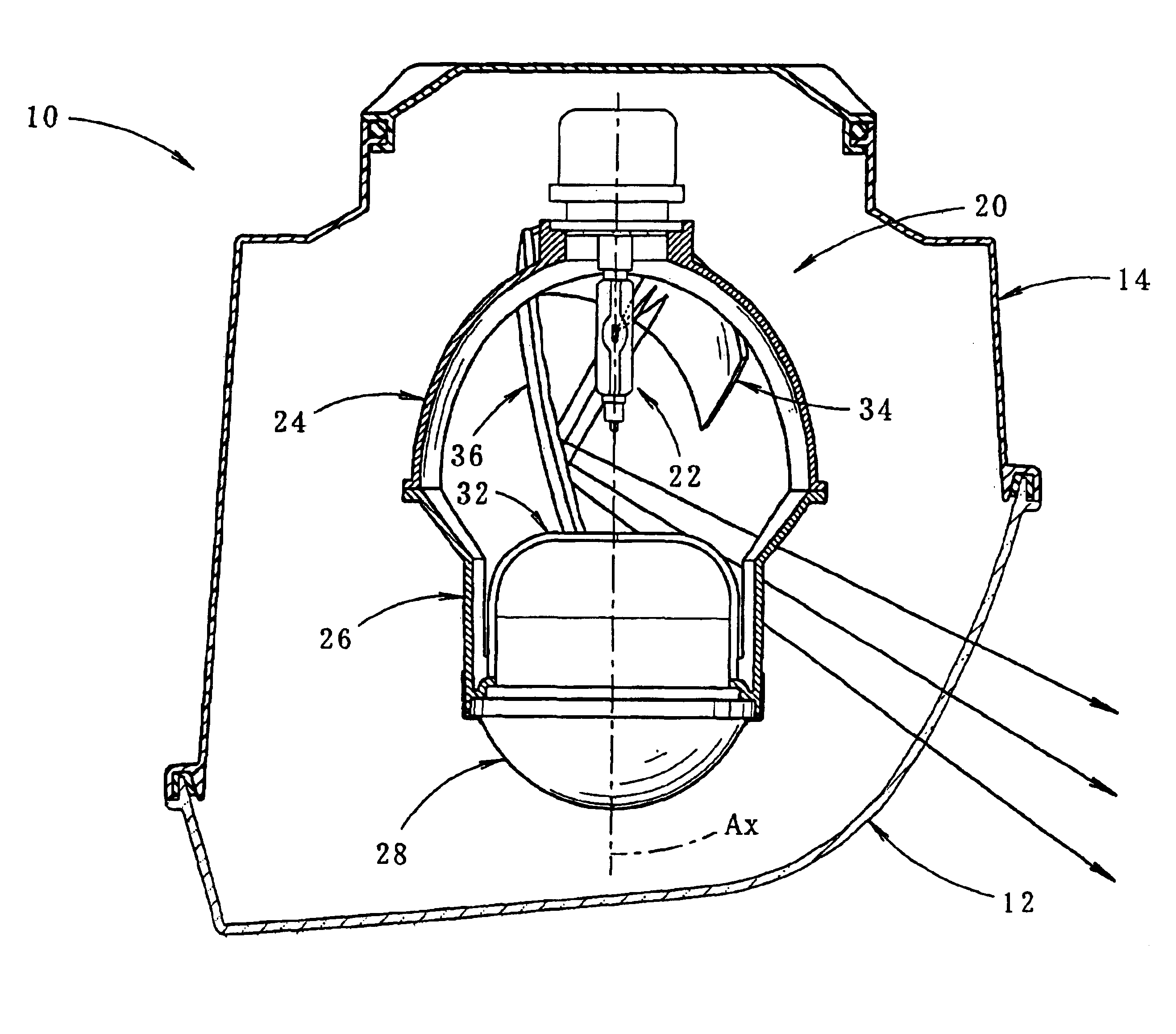
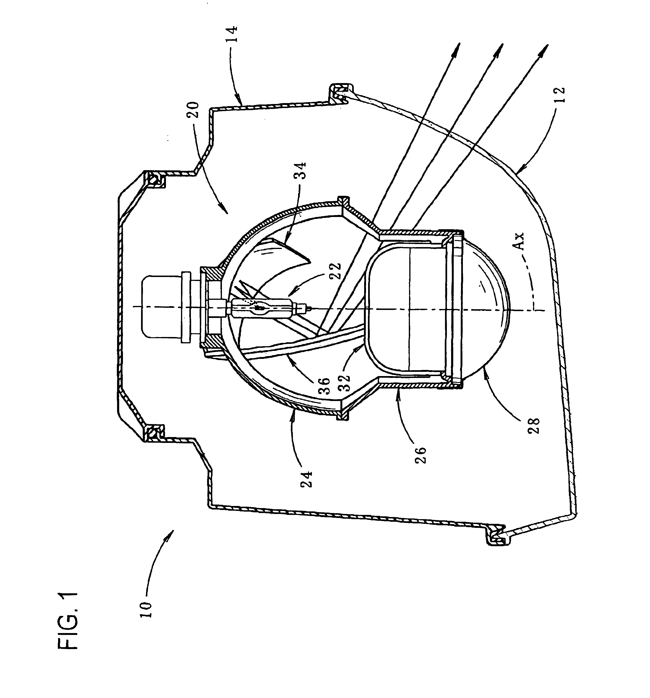
[0042]As described in detail above, the vehicular headlamp 10 is constructed such that a beam is radiated forward in a low-beam light distribution pattern P(L) including the cut-off line CL by the projection-type lamp unit 20. The first additional reflector 34 for reflecting light from the discharge light source 22a forward is provided below the discharge bulb 22 of the lamp unit 20. Furthermore, the second additional reflector 36 for reflecting reflected light from the first additional reflector 34 leftward to form the additional light distributional pattern P(A), which partially overlaps the lateral portion of the low-beam light distribution pattern P(L), is positioned in front of the first additional reflector 34. Accordingly, road zones on the sides of the vehicle and the like can be sufficiently illuminated, thereby providing improved visibility to the sides of the vehicle.

[0043]According to the first embodiment, although a lower portion of the reflector 24 is eliminated in or...

second embodiment

[0049]Next, a description will be given of the invention.

[0050]FIG. 5 is a cross-sectional view taken in a horizontal plane showing a lamp unit 40 constructed according to the second embodiment.

[0051]As shown in the drawing a lamp unit 40 according to the second embodiment is the same as the lamp unit 20 of the first embodiment with respect to basic construction, but differs in the construction of first and second additional reflectors 42 and 44.

[0052]The first additional reflector 42, which is identical in structure to the first additional reflector 34 in the first embodiment, is mounted below the discharge bulb 22 and reflects light from the discharge light source 22a forward. However, the reflecting surface 42a of the first additional reflector 42 has the position of the first focal point F1 of the reflector 24 as a focal point, and is formed as a paraboloid of revolution having the optical axis Ax as its central axis. Therefore, light from the discharge light source 22a is refle...


PUM


Abstract

A vehicular headlamp which radiates a beam forward in a predetermined low-beam light distribution pattern using a projection-type lamp unit and with which visibility to the sides of a vehicle is improved without having a significant effect on the formation of the low-beam light distribution pattern. A first additional reflector for reflecting light from a discharge light source of a discharge bulb forward is disposed below a discharge bulb of the projection-type lamp unit. A second additional reflector for reflecting reflected light from the first additional reflector to one side is provided in front of the first additional reflector. An additional light distribution pattern that partially overlaps a side portion of the low-beam light distribution pattern is formed, thereby providing improved illumination of road zones to the sides of the vehicle. Although a lower portion of a reflector is cut away in order to receive both additional reflectors, this does not significantly affect formation of the low-beam light distribution pattern.

Description

REFERENCE TO RELATED APPLICATIONS[0001]Not applicableSTATEMENT REGARDING FEDERALLY SPONSORED RESEARCH OR DEVELOPMENT[0002]Not applicableREFERENCE TO SEQUENCE LISTING A TABLE, OR A COMPUTER PROGRAM LISTING COMPACT DISK APPENDIX[0003]Not applicableBACKGROUND OF THE INVENTION[0004]The present invention relates to a vehicular headlamp employing a projection-type lamp unit.[0005]Conventionally, a vehicular headlamp constructed so as to radiate a beam forward using, a projection-type lamp unit has been known.[0006]The projection-type lamp unit is constructed so as to converge and reflect light from a light source, which is disposed on an optical axis extending in the lengthwise direction of a vehicle forward towards the optical axis using a reflector, and radiate the reflected light to the front of the lamp via a projection lens provided in front of the reflector. If this projection-type lamp unit is constructed for low beam radiation, a shade for partially blocking reflected light from t...

Claims


Application Information

Patent Timeline
Patent Type & Authority Patents(United States)
IPC IPC(8): F21V7/00F21S8/10F21S8/12F21V13/00F21W101/10F21Y101/00
CPCF21S48/1388F21S41/172F21S41/255F21S41/321F21S41/337F21S41/365F21S41/43F21W2102/19
Inventor TAKADA, KENICHIOKAWA, KOJI
Owner KOITO MFG CO LTD
Learn More