Compressor with terminal assembly having dielectric material

a terminal assembly and compressor technology, applied in the direction of connection contact member material, positive displacement liquid engine, coupling device connection, etc., can solve the problems of compressor housing leakage of pressurized gas at the terminal assembly, short circuit or arc development along the conductive path, resistive heating of deposits, etc., to achieve the effect of less assembly steps, less time or effort, and less investmen

Inactive Publication Date: 2005-06-28
TECUMSEH PROD CO
View PDF30 Cites 49 Cited by
  • Summary
  • Abstract
  • Description
  • Claims
  • Application Information

AI Technical Summary

Benefits of technology

[0013]The present invention further provides a method for insulating an electrical connection within a hermetically sealed compressor assembly, including placing a dielectric gel into a terminal assembly having at least one conductor pin, placing the dielectric gel into a cluster block assembly having at least one connector, connecting the cluster block assembly and the terminal assembly together whereby the pin and the connector are electrically coupled, and allowing the dielectric gel to cure into a substantially solid state.
[0015]One advantage provided by the present invention is that by filling substantially all free volume within the cluster block assembly, and the cavity defined by the cluster block and the terminal assemblies, with the insulative gel, conductive deposits are prevented from entering and from accumulating on the interior surfaces of the terminal and cluster block assemblies. By filling all free volume within the cluster block assembly and the cavity defined by the cluster block and terminal assemblies with the insulative filling, no volume is left in which debris may enter and accumulate. This prevention of accumulation of deposits in turn precludes the formation of a conductive path between elements at different electrical potentials and an arc therealong.
[0016]An additional advantage provided by the present invention is that the insulative filling covers the fused glass insulators of the terminal assembly. This covering of the insulators helps prevent the potential melting thereof and subsequent leakage of pressurized gas.
[0017]Another advantage provided by the present invention is that it requires few additional assembly steps and little additional investment. In the first embodiment, the insulative filling is placed in each of the cluster block assembly and the cavity defined between the cluster block assembly and the terminal assembly prior to their connection to each other, requiring little additional time or effort. In the second embodiment, the insulative filling is injected into the cluster block assembly after the final connections between the cluster block and the terminal assembly are made, and subsequently flows into the cavity, requiring even less additional time or effort.

Problems solved by technology

These deposits may provide a conductive path between elements having different electrical potentials, thereby causing a short circuit or arc to develop along the conductive path.
Such arcing results in the resistive heating of the deposits along the conductive path, in turn heating the elements on which the deposits collect.
Such heating is known to sometimes cause the fused glass insulators surrounding the conductor pins to melt, thereby causing the compressor housing to leak pressurized gas at the terminal assembly.
However, some prior cluster block assemblies may not completely preclude the formation of a conductive path between the lead wire ends and / or electrical connectors within the cluster block, and the terminal body or compressor housing.
A problem associated with prior cluster block assemblies which sealably engage the terminal assembly in this manner is that they may be improperly installed, the proper seating of the block relative to the terminal assembly being hindered by the interference fit between the terminal body and the cluster block, or the O-ring therebetween.
A problem with such cluster block assemblies is that the conductor pins and the interior of the housing may not be completely sealed from each other to prevent the collection of the conductive materials on the terminal assembly, thereby allowing the previously mentioned arcing to occur.
Another problem is that this sealing method requires additional steps in the assembly process, such as placing the layers on the respective parts prior to completion of the assembly, or that the process would require additional time for the seals to cure before completion of the assembly.

Method used


Image

  • Compressor with terminal assembly having dielectric material
  • Compressor with terminal assembly having dielectric material
  • Compressor with terminal assembly having dielectric material

Examples


Embodiment Construction

[0028]For the purposes of promoting an understanding of the principles of the invention, reference will now be made to the embodiments illustrated in the drawings and specific language will be used to describe the same. It will nevertheless be understood that no limitation of the scope of the invention is thereby intended.

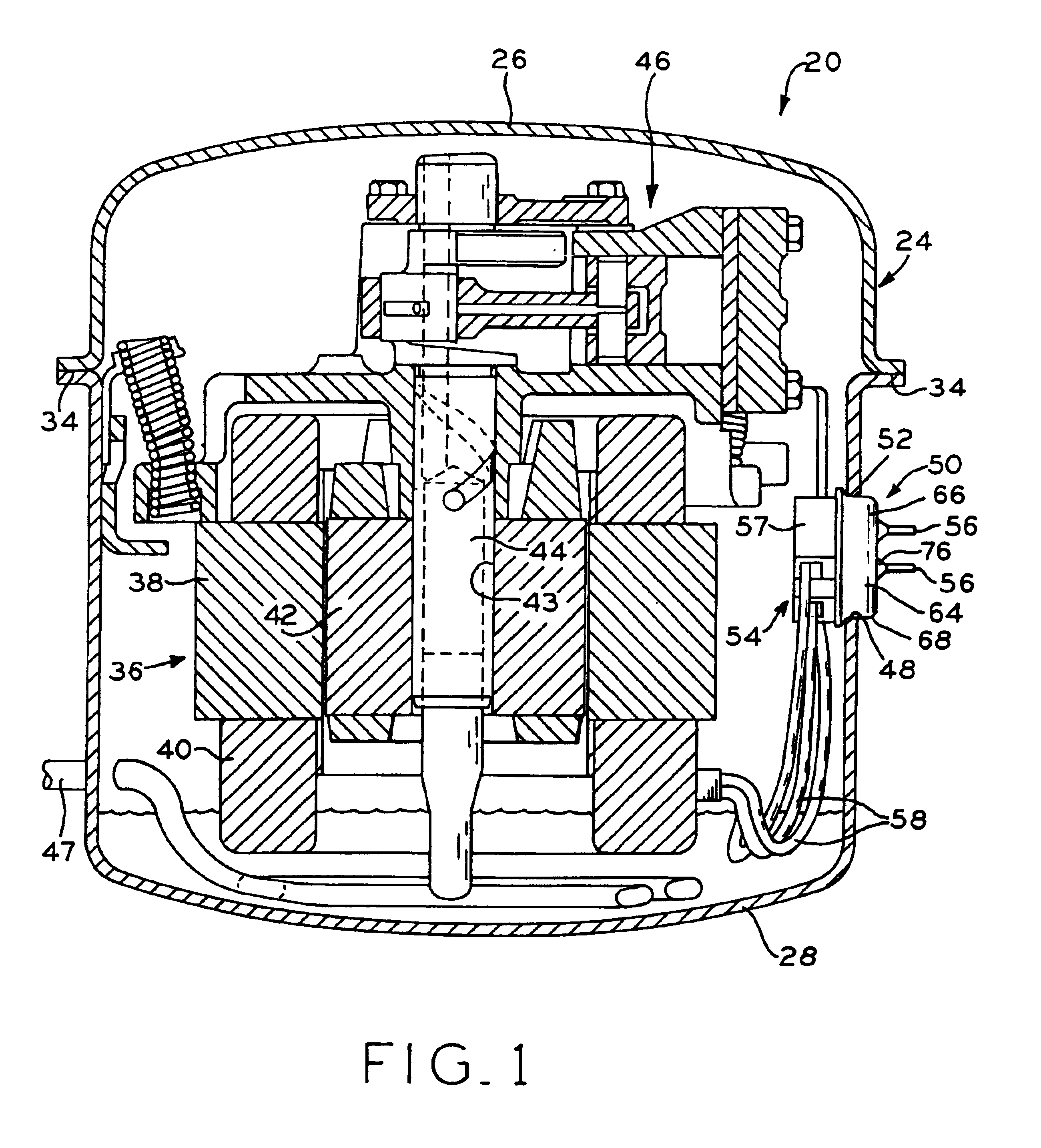
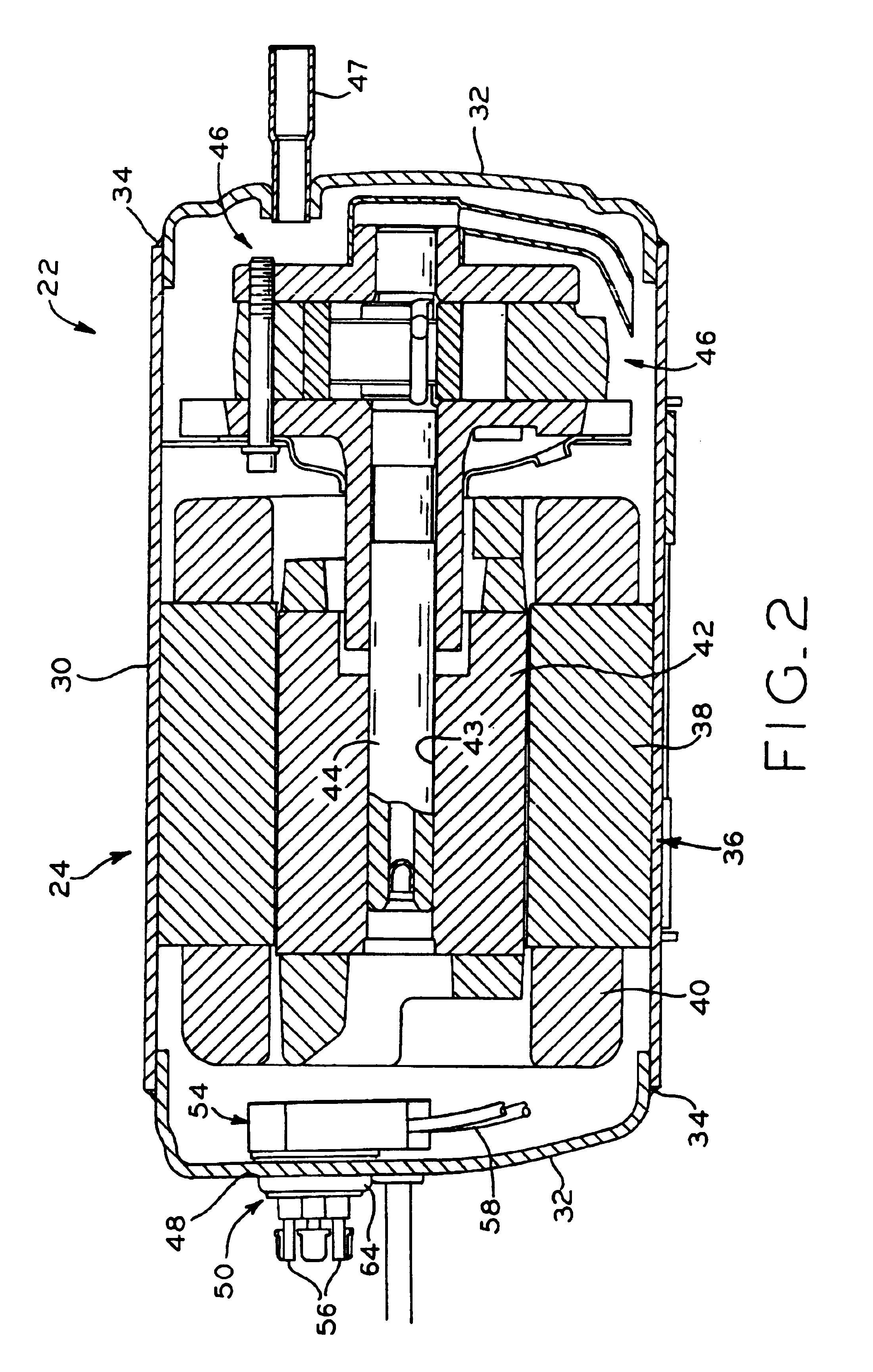
[0029]Referring to FIGS. 1 and 2, reciprocating compressor assembly 20 and rotary compressor assembly 22 are shown as examples of types of hermetic compressor assemblies in which the present invention may be advantageously used. Other hermetic compressor types, such as, for example, a scroll compressor assembly, may also benefit from use of present invention.

[0030]The compressor assembly, which may be part of a refrigeration system (not shown) also comprising heat exchangers, an expansion device and refrigerant conveying lines, receives refrigerant substantially at suction pressure and discharges it substantially at discharge pressure. The compressor assembly may b...


PUM


Abstract

A hermetically sealed compressor assembly including a housing, an electric motor located in the housing, a compression mechanism located in the housing and operatively coupled to the motor, and a terminal assembly comprising a cup-shaped terminal body and having electrically conductive pins extending therethrough. The cup-shaped terminal body extends through and is sealingly attached to the housing. A cluster block assembly is in communication with the terminal assembly and includes a cluster block fitted to the terminal body, the cluster block having free volume therein. The pins are electrically connected to the motor through the cluster block assembly. A cavity is defined between the interior of the cup-shaped terminal body and the cluster block, and a dielectric material substantially fills at least one of the cavity and the cluster block free volume. The cluster block assembly may also include one or more apertures to provide for the introduction of the dielectric material which may be introduced after the mating of the connectors.

Description

BACKGROUND OF THE INVENTION[0001]1. Field of Invention[0002]The present invention relates to electrical connections internal to hermetic compressor assemblies, particularly with regard to connectors designed to protect against electrical arcing across carbon deposits which may be formed within the compressor assembly, and methods of providing arc prevention within hermetic compressor assemblies.[0003]2. Description of the Related Art[0004]The terminal assembly extends through the sealed shell, or housing, of a hermetic compressor and includes a terminal body and a plurality of conductor pins which extend through apertures located in the terminal body. The terminal body is usually welded or brazed into an aperture provided in the compressor assembly housing. The conductor pins are secured within these apertures and are electrically insulated from the terminal body and the housing by fused glass insulators. An electric motor having a stator and a rotor is located within the housing, w...

Claims


Application Information

Patent Timeline
Patent Type & Authority Patents(United States)
IPC IPC(8): F04B39/12H01R13/52H01R13/533H02K5/22
CPCF04B39/121F04B39/123H01R13/5216H01R13/533Y10S439/934Y10S439/942Y10S439/94Y10S439/936H02K5/225F04C23/008F04C18/02F04C18/356F04C2240/803
Inventor HERRICK, TODD W.BUNCH, RICK L.
Owner TECUMSEH PROD CO
Why Eureka
Try Eureka