Receptacle for holding an active substance and corresponding closure and container with such a receptacle

a technology for storing containers and active substances, which is applied in the direction of preventing decay, caps, separation processes, etc., can solve the problems of contaminating goods contained therein, the mechanical connection between the canister body and the cap might not be strong enough, and the problem of mechanical assembly of the canisters is sometimes problemati

Pending Publication Date: 2022-10-06
AIRNOV INC
View PDF0 Cites 0 Cited by
  • Summary
  • Abstract
  • Description
  • Claims
  • Application Information

AI Technical Summary

Benefits of technology

[0013]It is an object of the invention to provide a receptacle for an active substance which is easy to manufacture, and safely avoids potential leakage of the active substance and allows a sufficient transport of the gaseous substances to be trapped between the outside and the inside of the receptacle.

Problems solved by technology

Mechanically assembled canisters are sometimes problematic in that the mechanical connection between the canister body and the cap might not be strong enough to withstand a deformation of the canister under load conditions.
Such load conditions might occur during use in a container filled with particulate matter or under exceptional circumstances, e.g. when the container is inadvertently dropped onto a hard surface.
The resulting undesired opening of the canister upon deformation has the consequence that its contents, e.g. dehydrating agents or oxygen adsorbents, might be introduced into the interior of the container and might contaminate goods contained therein, like drugs.
However, the welding or any other comparable heat treatment to a porous membrane might be problematic because either the welded connection is weak or the membrane might be more sensitive to heat than the canister body.
Accordingly, a heat treatment of a porous membrane might negatively influence its density, i.e. its permeability, and its behavior at the welded seams due to the degradation of the material of the membrane under an excessive thermal load.
As a further problem, the functional material inside the canister might also be negatively affected by elevated temperatures so that a heat treatment is not feasible under certain circumstances.
A mechanical assembly followed by a welding of the contact region between the canister body and the cap involves a further manufacturing step and increases the production costs.
A further technical problem of perforated membranes is that powder active materials can contain particles or pieces of particles which can be friable and / or small enough to pass through the perforations, leading to a contamination of the content of the container in which the canister is introduced.
One of the major drawbacks of such a solution in the prior art is the additional manufacturing step of attaching the disc and the associated quality control required because a safe attachment of the disc is essential in order to avoid a leakage of the active material and the undesired pollution of the articles contained in the container.
In case of drugs, such pollution can be very problematic.
One of the main drawbacks of such solutions is the possibly insufficient holding force of the permeable disc, resulting in leakage of the absorbent material and pollution of the drugs contained in the container.

Method used


Image

  • Receptacle for holding an active substance and corresponding closure and container with such a receptacle
  • Receptacle for holding an active substance and corresponding closure and container with such a receptacle
  • Receptacle for holding an active substance and corresponding closure and container with such a receptacle

Examples


first embodiment

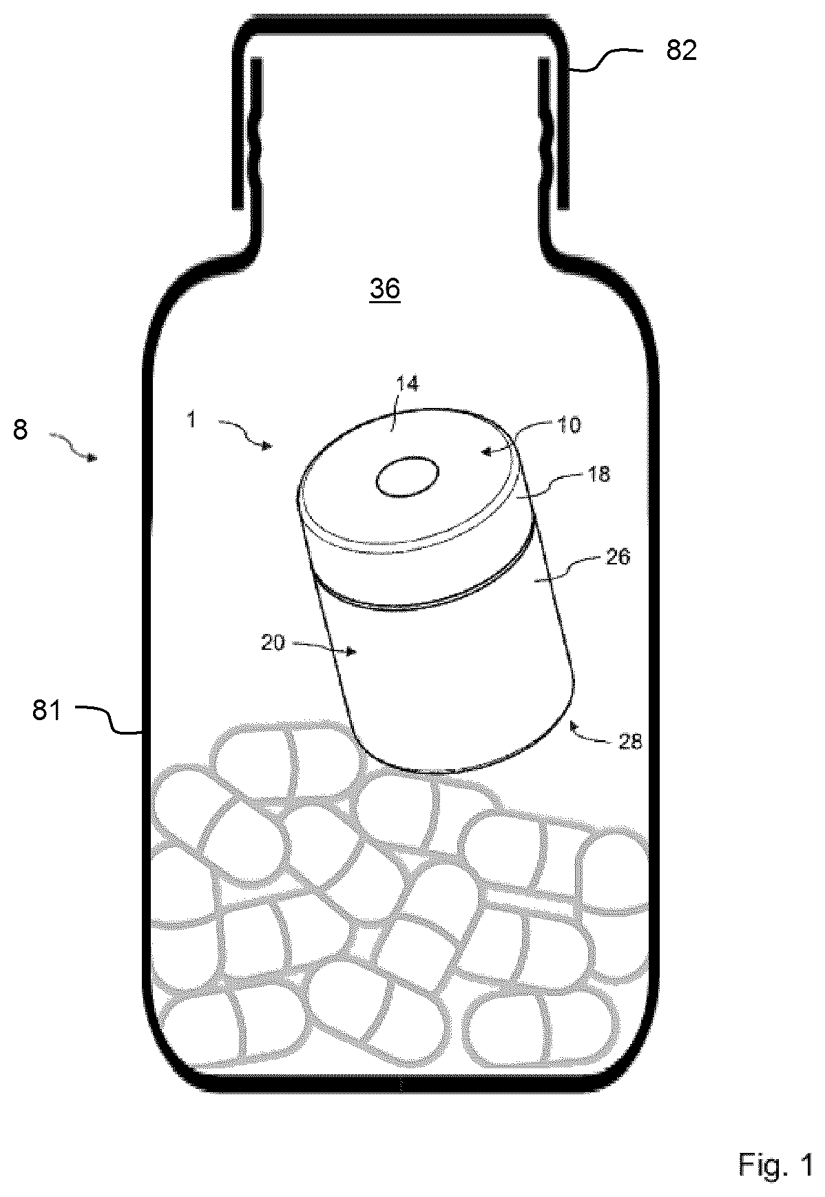
[0085]The sidewall 26 of the canister body 20, which is integrally formed with the bottom wall 28, has a substantially tubular shape and extends perpendicularly from the bottom wall 28. In the first embodiment as shown in FIGS. 1 to 6, the outer diameter of an upper portion 21 of the sidewall 26 is selected such that it can be placed, at least partially, inside the skirt 18.

[0086]The sidewall 26 of the canister body 20 is dimensioned so that the skirt 18 of the cap 10 is held by a snap-fit connection (protruding part 210 on the upper portion 21 of the sidewall 26 in interaction with the protruding part 110 on the inner side of the skirt 18 of the cap 10).

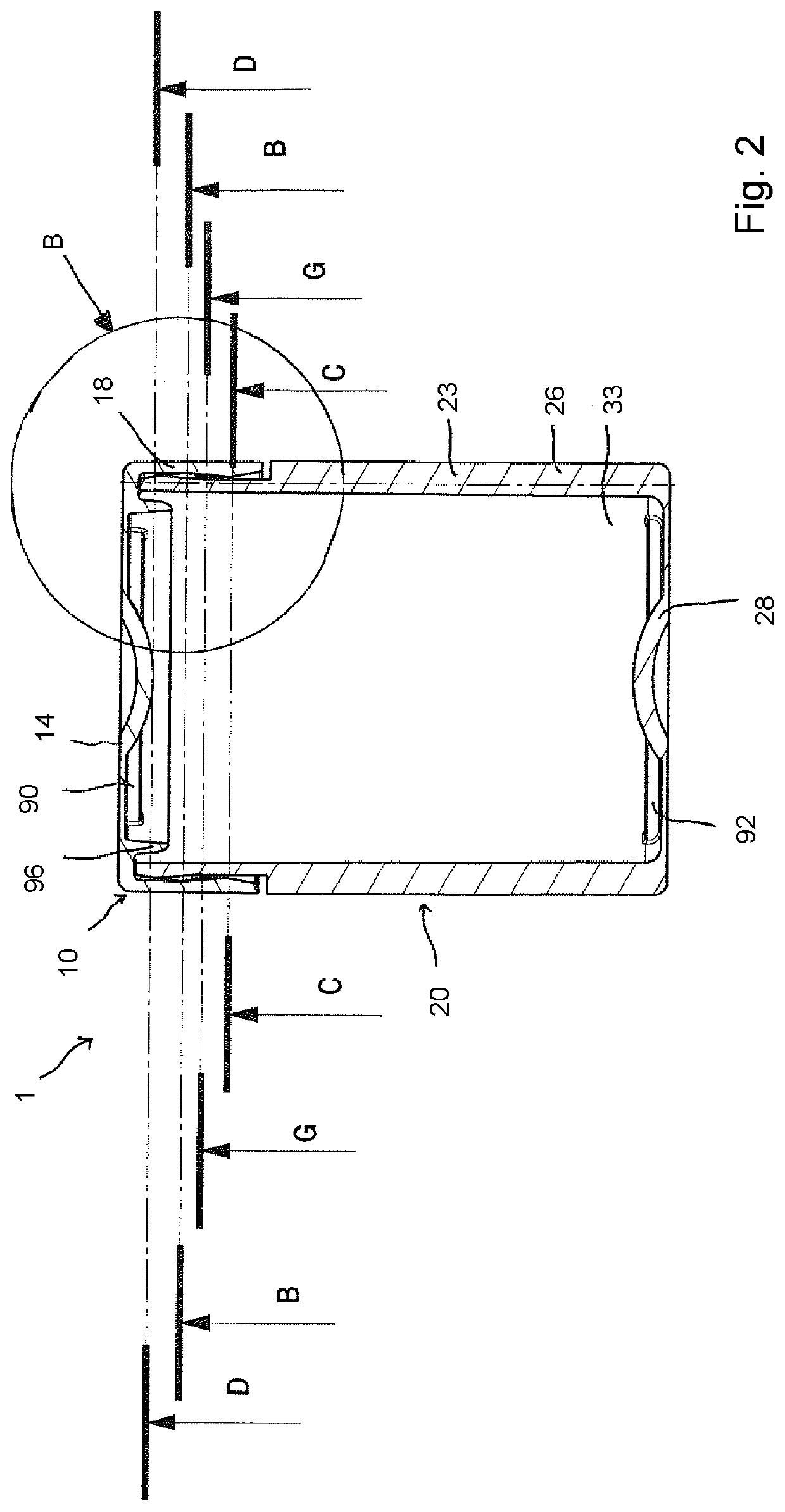
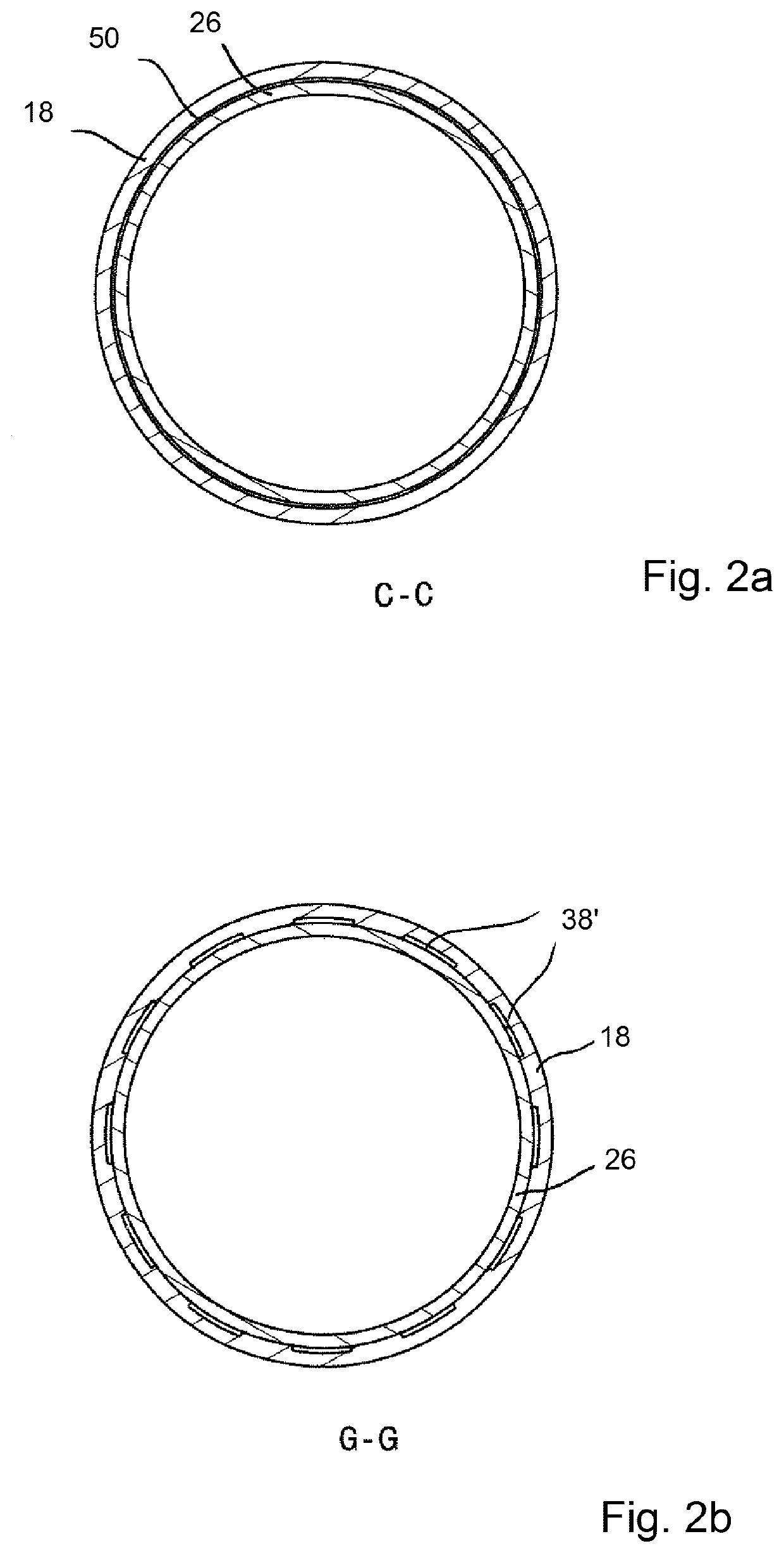
[0087]In the embodiment according to FIG. 1, a snap-fit connection is used. This can be best seen in the cross-sectional view in FIG. 2 which shows the canister body 20 with the bottom 28 and sidewall 26, and the cap 10 with its top wall 14 and the skirt 18. In order to stiffen the overall structure, FIG. 2 additionally shows a rein...

second embodiment

[0101]Another embodiment of the invention is described in FIGS. 7A to 12. One major difference is the cross-sectional shape of the canister 1 which, in the second embodiment, is of a roughly square shape with flattened or rounded corners. A further major difference lies in the fact that, in the embodiment according to FIGS. 7A to 12, the skirt of the cap is surrounded by the sidewall of the canister 1. These and further differences will be detailed below.

[0102]In the two views of FIGS. 7A and 7B, the receptacle is a canister 1 which also consists of two elements. The cap 10 closes the canister body 20. The canister body 20 comprises a bottom wall 28 and a sidewall 26 which extends perpendicularly from the bottom wall 28 and is provided as a unitary structure with the bottom wall 28. The cap 10 closes an open end of the sidewall 26 of the canister body 20.

[0103]In the embodiment according to FIGS. 7A to 12, the cap 10 as shown in FIGS. 9A and 9B has a top wall 14 and a skirt 18 which...


PUM

PropertyMeasurementUnit
heightaaaaaaaaaa
heightaaaaaaaaaa
heightaaaaaaaaaa

Abstract

A receptacle forming a chamber partially filled with an active substance, wherein the receptacle is a body and a cap which closes the body. The cap includes a top wall with a first main side facing an interior of the chamber and a skirt formed with the first main side of the top wall. The body includes a bottom wall and a sidewall. The skirt and the sidewall surround one another in contact with each other. The walls surrounding the chamber include the bottom wall, the top wall and either the skirt or the sidewall. At least one ventilation path is provided between the skirt and the sidewall, such that the ventilation path connects the chamber with the outside atmosphere.

Description

FIELD OF THE INVENTION[0001]The invention relates to a receptacle intended to regulate the atmosphere in a container for storing sensitive products, the receptacle being designed to be at least partially filled with an active substance and permit gases and vapors to enter the receptacle for interacting with the active substance. The invention also relates to a closure for closing an open end of a container body part comprising such receptacle and a container for storing loose products comprising such receptacle.BACKGROUND OF THE INVENTION[0002]A number of small desiccant receptacles, also called canisters, have been disclosed, which are formed from gas and liquid impermeable body portions which can be perforated and onto which are secured one or more perforated end caps. These canisters generally contain a desiccant material which adsorbs moisture from the air as the air flows through the perforations provided in an end cap of the desiccant canister.[0003]Such canisters are used in ...

Claims


Application Information

Patent Timeline
Patent Type & Authority Applications(United States)
IPC IPC(8): B65D51/30B65D51/16B65D41/16B65D81/26B01D53/04
CPCB65D51/30B65D51/1622B65D41/16B65D81/268B01D53/0415B65D43/00B01D53/26B01D53/261B01D53/263B01D2257/104B01D2257/90B01D2253/102B01D2253/104B01D2253/106B01D2253/11B01D2253/108B01D2251/302B01D2251/402B01D2251/404B01D2253/202B01D2259/4525A61L9/04
Inventor LEBON, JACQUYLOGEL, VALEREBOIS, DOMINIQUE
Owner AIRNOV INC
Why Eureka
Try Eureka