Constant velocity universal joint

a constant velocity, universal joint technology, applied in the direction of shaft and bearings, rotary machine parts, rolling contact bearings, etc., can solve problems such as affecting sliding resistance, and achieve the effect of easy design

Inactive Publication Date: 2005-06-28
NTN CORP
View PDF14 Cites 17 Cited by
  • Summary
  • Abstract
  • Description
  • Claims
  • Application Information

AI Technical Summary

Benefits of technology

[0011]An object of the present invention is to make it easy to design, so that the sliding res

Problems solved by technology

This greatly affects t

Method used


Image

  • Constant velocity universal joint
  • Constant velocity universal joint
  • Constant velocity universal joint

Examples


Embodiment Construction

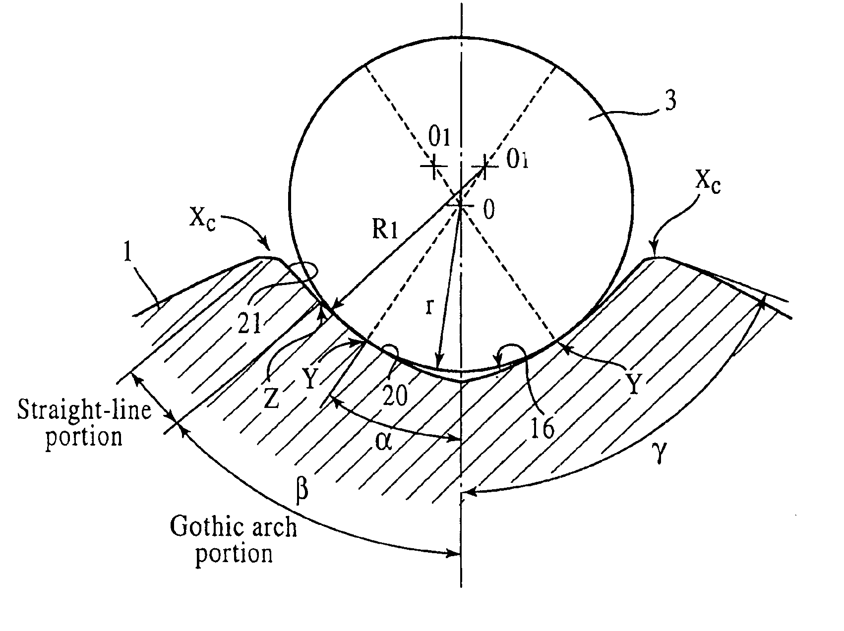
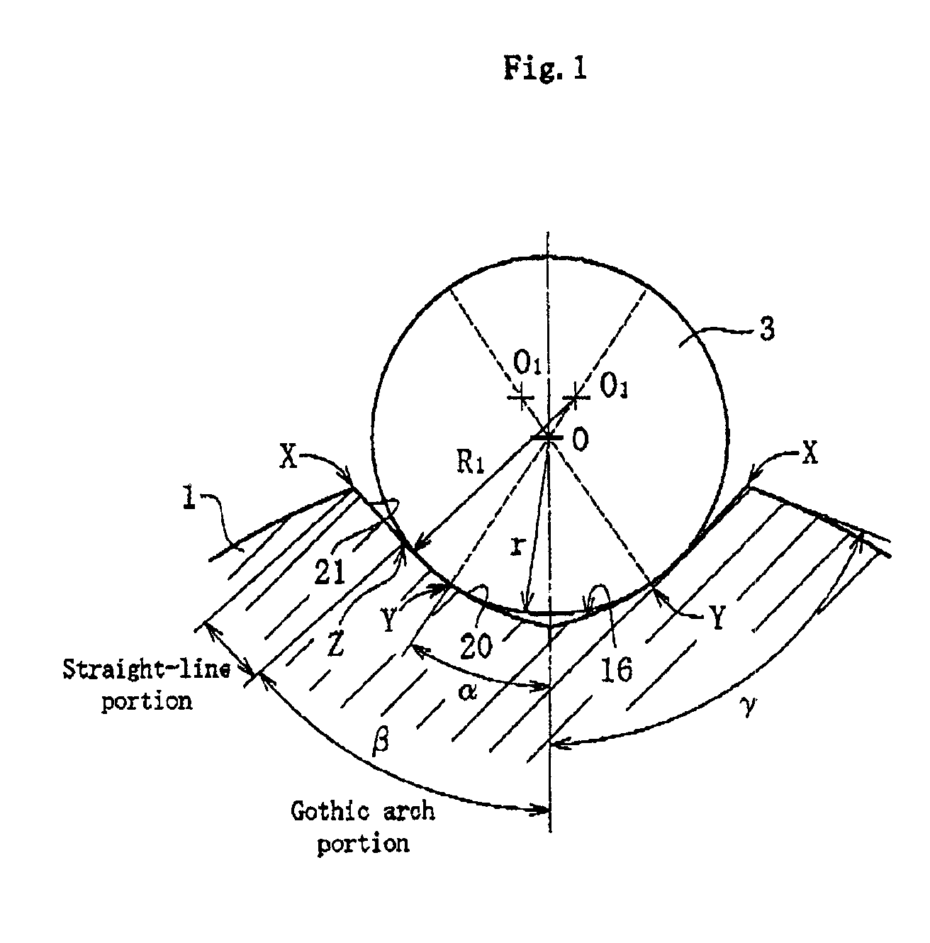
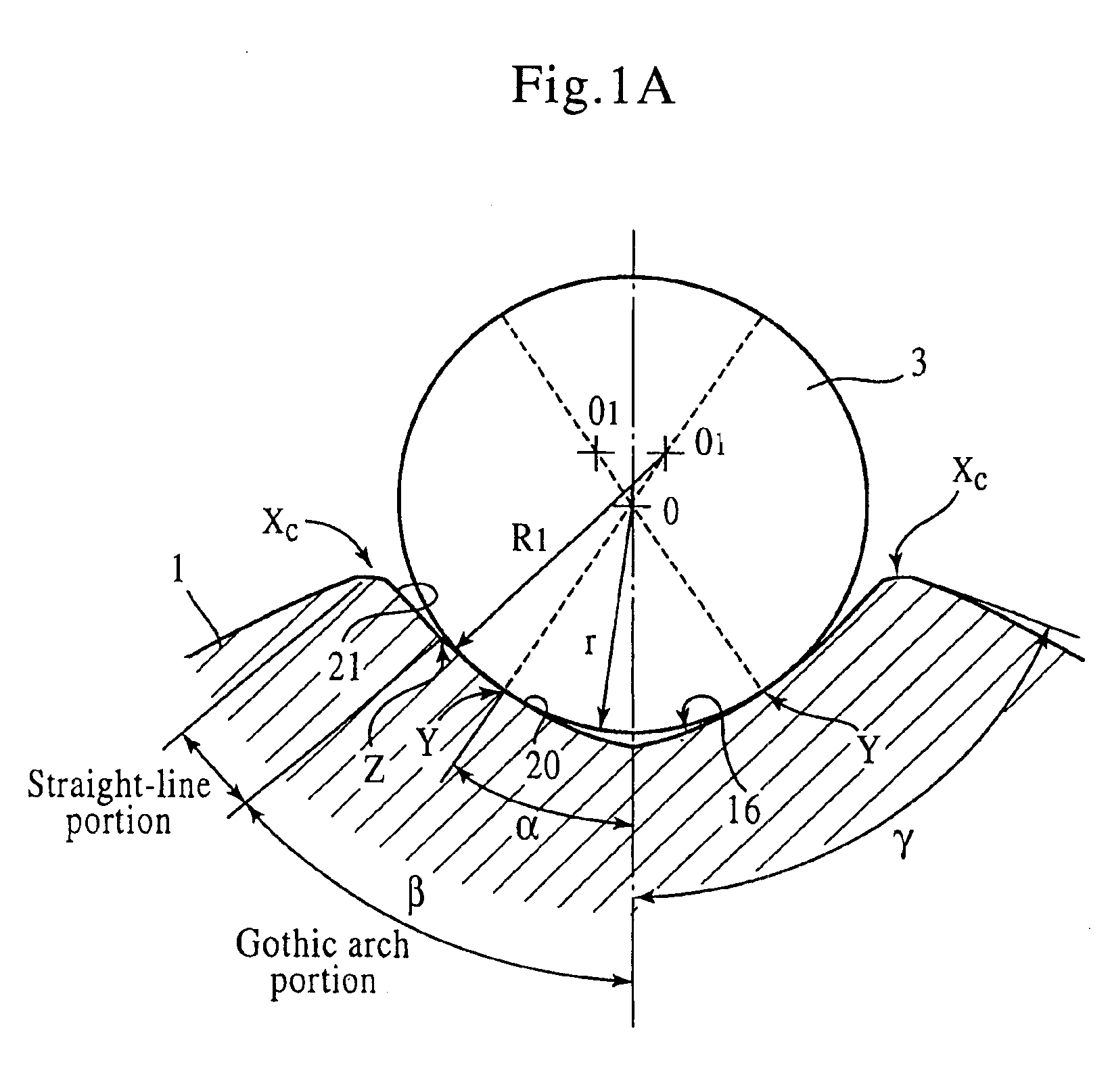
[0026]An embodiment of the present invention is shown in FIG. 1. In this figure, only a track groove 16 of an inner ring 1 and a ball 3 are shown in an enlarged state, because the only point that this embodiment is different from a conventional example (refer to FIG. 5), is in the shape of the track groove 16 of the inner ring 1. In this embodiment, reference to drawings and repeated descriptions are omitted for portions other than those shown, because they are the same as in conventional ones (refer to FIG. 4).

[0027]The cross-sectional shape of the track groove 16 of the inner ring 1 is constituted by a Gothic arch shape up to a location Z exceeding the contact point Y where the ball 3 angular-contacts therewith, and a straight line shape continuously extending in a direction of the tangent line at the location Z exceeding the contact point Y, between the location Z exceeding the contact point Y and the shoulder portion X of the track groove 16.

[0028]This Gothic arch portion 20 has...


PUM


Abstract

It is made easy to design so that the sliding resistance, when subjected to an impact in the axial direction, is kept within a prescribed value. A constant velocity universal joint is provided, which has track grooves extending in the axial direction on the outer circumference surface of the inner ring, and formed in an intersecting arrangement, and which also embeds balls in these track grooves. In this constant velocity universal joint, the cross-sectional shape of the track groove of the inner ring is constituted by a Gothic arch portion which is a Gothic arch shape up to a location that exceeds a contact point where the groove angular contacts with the ball, and a straight-line portion which is formed continuously with the Gothic arch portion, between the location exceeding the contact point and a shoulder portion of the track groove, and which extends in the direction of the tangent line at the location that exceeds the contact point.

Description

BACKGROUND OF THE INVENTION[0001]1. Field of the Invention[0002]The present invention relates to a Lobro-type constant velocity universal joint that is suited for a propeller shaft used in four-wheel-drive cars and front-engine rear-wheel-drive cars.[0003]2. Description of the Related Art[0004]In four-wheel-drive cars and front-engine rear-wheel-drive cars, a so-called Lobro-type (or cross-groove type) constant velocity universal joint is used, to realize a propeller shaft construction that can cope with an angle change due to a change in the relative location between the transmission and the differential gear.[0005]This Lobro-type constant velocity universal joint is shown in FIG. 4 as an example. This constant velocity universal joint has an inner ring 1, an outer ring 2, a ball 3, and a cage 4 as main components. The inner ring 1 has a stub shaft (not shown) of a propeller shaft intermeshed by serration onto its central hole 5, and has a plurality of track grooves 6 formed on its...

Claims


Application Information

Patent Timeline
IPC IPC(8): F16D3/16F16D3/223F16D3/20
CPCF16D3/223Y10S464/906F16D2003/22309
Inventor KOBAYASHI, MASAZUMI
Owner NTN CORP
Why Eureka
Try Eureka