
Switching power supply

Inactive Publication Date: 2005-06-28
TESLA INC
View PDF6 Cites 16 Cited by
  • Summary
  • Abstract
  • Description
  • Claims
  • Application Information

AI Technical Summary

Benefits of technology

[0009]The invention provides current controlled switching power supplies, used for example, as energy storage devic

Problems solved by technology

However, a completely discharged capacitor appears as a dead short, e.g., 0 volts at the output, which causes excessive current surges that may damage the charging circuit.
These current inrushes occur for a relatively long time since as the voltage at the output is near zero, the transformer takes considerable time to discharge.
Disadvantageously, the majority of the initial energy is not transferred to the capacitor.
This can lead to excessive charge up times while the battery recovers and in some cases, the battery may not be able to supply enough current in the charging cycle to reach the predetermined level.

Method used


Image

  • Switching power supply
  • Switching power supply
  • Switching power supply

Examples


Embodiment Construction

[0022]The following description is not to be taken in a limiting sense, but is made merely for the purpose of describing the general principles of the preferred embodiments. The scope of the invention should be determined with reference to the claims.

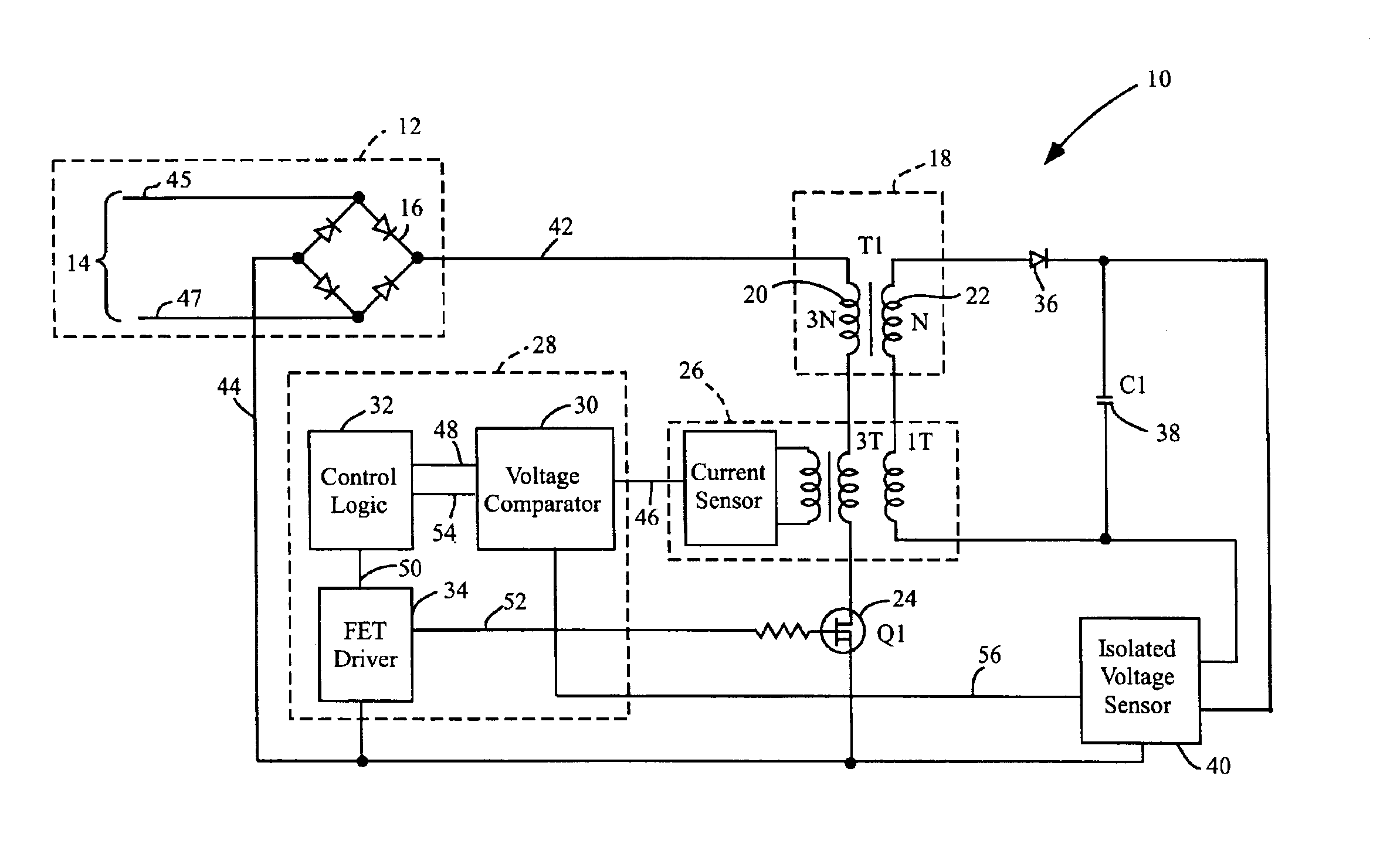
[0023]Switching power supplies, used for example, as energy storage device charging circuits, are provided herein that provide maximum energy transfer from the switching power supply to the intended load to be coupled thereto. In one embodiment, the switching power supply is current controlled and is used to charge energy storage capacitors. In preferred embodiments, the switching power supply uses an AC input source to charge high value energy storage capacitors.

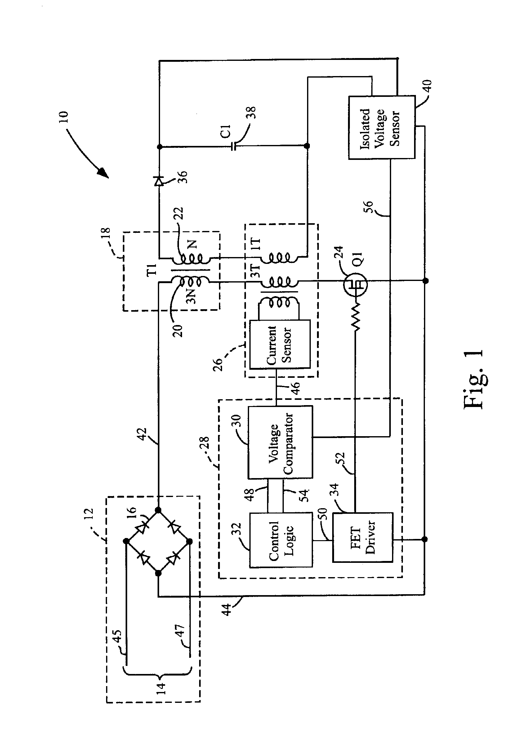
[0024]Referring first to FIG. 1, a block diagram is shown of a self-oscillating or switching power supply 10 (which may be referred to as a capacitor charging circuit when uses to charge energy storage capacitors) in accordance with one embodiment of the invention. Illustrated ...


PUM


Abstract

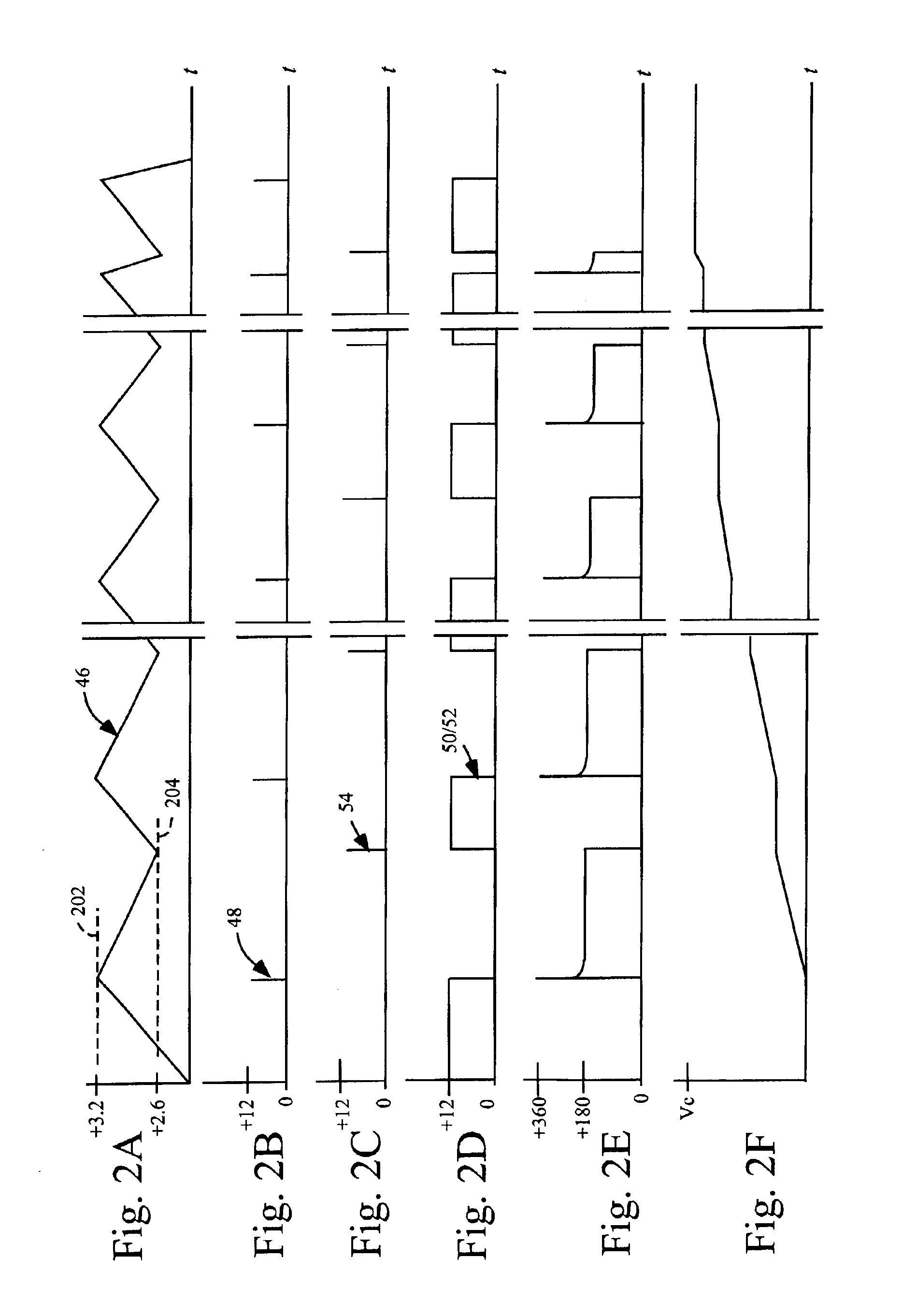
Self-oscillating, current controlled switching power supplies, used for example, as energy storage device charging circuits, and related methods are provided herein. In one implementation, a switching power supply comprises a power transformer having a primary and a secondary, a switching element that switches a voltage source to the primary, and a control circuit that controls the operation of the switching element in response to the measured primary current and secondary current. The switching element disconnects the voltage source from the primary when the primary current reaches a first threshold, causing the secondary current to conduct. The switching element switches back to the primary when the secondary current drops to second threshold. The switching power supply oscillates between charging and discharging the power transformer. In one embodiment, a high value energy storage capacitor is coupled to the secondary and is charged with the secondary current.

Description

BACKGROUND OF THE INVENTION[0001]1. Field of the Invention[0002]The present invention relates generally to power supplies, and more specifically to power supplies for charging capacitors.[0003]2. Discussion of the Related Art[0004]Capacitors are energy storage devices that are capable of storing energy, which may be very rapidly discharged and then subsequently recharged. Conventional capacitor charging circuits typically utilize a DC source, such as a battery, which is used to charge the capacitor. Typically, current is allowed to flow into a primary winding of the transformer to store energy, which is then discharged into the capacitor in the form of a charging current flowing through the secondary winding of the transformer into the capacitor to be charged. Such charging circuits oscillate between storing energy into the transformer (a charging cycle of the transformer) and then transferring this energy into the capacitor (a discharging cycle of the transformer) until it is charg...

Claims


Application Information

Patent Timeline
IPC IPC(8): H02M1/00H02M3/338H02M3/24H02M1/42
CPCH02M1/4258H02M3/3385Y02B70/126Y02B70/10
Inventor THRAP, GUY C.
Owner TESLA INC
Learn More