Bumper structure for a motor vehicle

a technology for bumpers and motor vehicles, applied in bumpers, vehicle components, pedestrian/occupant safety arrangements, etc., can solve the problems of bone fracture in the lower legs of pedestrians, pedestrians' knees during collisions with motor vehicles,

Inactive Publication Date: 2005-07-05
CALSONIC KANSEI CORP
View PDF11 Cites 14 Cited by
  • Summary
  • Abstract
  • Description
  • Claims
  • Application Information

AI Technical Summary

Benefits of technology

[0016]Because the first and the second impact absorption members are formed to be integral with each other b...

Problems solved by technology

This results in the upper portion being deformed to retreat backward of the vehicular body to a greater extent than the lower portion, which prevents knees of the pedestrian from being bent toward a direction opposite to their natural bending direction, and broken.
The above known conventional bumper structure, however, encounters a problem in that because the upper portion and the lower portion, smaller in the longitud...

Method used


Image

  • Bumper structure for a motor vehicle
  • Bumper structure for a motor vehicle
  • Bumper structure for a motor vehicle

Examples


first embodiment

[0035]Next, an operation and advantages of the bumper structure 100 of the first embodiment will be described with reference to FIGS. 3 and 4.

[0036]FIG. 3 shows a relationship with a pedestrian and the motor vehicle with the above constructed bumper structure 100 just before a collision between the pedestrian and the bumper structure, FIG. 4 shows a relationship with the pedestrian and the motor vehicle during a collision between the pedestrian and the bumper structure.

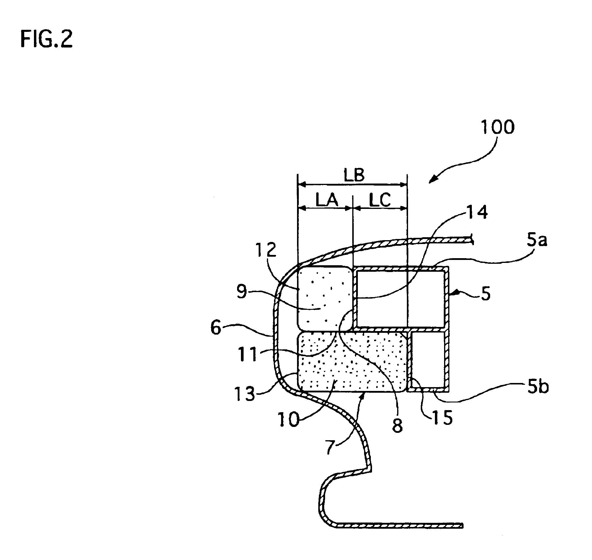
[0037]When the motor vehicle comes into contact with the pedestrian just after the state of FIG. 3, the bumper fascia 6 strikes his or her lower legs R. This impact force, applied to the bumper fascia 6 from the pedestrian, is transmitted to the impact absorber 7, i.e. both of the first and second impact absorption members 9 and 10 simultaneously.

[0038]As shown in FIG. 4, the impact force acts to press and deform the first and second impact absorption members 9 and 10 in the longitudinal direction of the vehicular bod...

second embodiment

[0042]Next, the invention will be described with reference to FIG. 5.

[0043]Referring to FIG. 5, in a bumper structure 100 of the second embodiment, the first and second impact absorption members 9 and 10 of the first embodiment are integrally formed into an impact absorber 16 by an injection molding machine using double injection molding, and other parts are the same as those of the first embodiment described above, whose descriptions are omitted for eliminating duplication.

[0044]Specifically, the impact absorber 16 has a flat front surface and a stepped rear surface 17 to mate with a stepped front surface 8 of a bumper reinforcement 5. The impact absorber 16 has an upper portion 19 and a lower portion 20 longer in a longitudinal direction of a vehicular body and projecting backward of the vehicular body with respect to the rear surface of the upper portion 19. The upper portion 19 is made of low density polyprophylene foam, while the lower portion 20 is made of high density polypro...

third embodiment

[0047]Next, the invention will be described with reference to FIG. 6.

[0048]Referring to FIG. 6, in a bumper structure 100 of the third embodiment, a front surface 23 of a bumper reinforcement 22 and a rear surface 27 of an impact absorber 24 are different from those of the first and second embodiments.

[0049]The bumper reinforcement 22 is made of metal sheet and has upper portion 22a and lower portion 22b integral with the upper portion 22a, which have closed sectional shapes, respectively. The bumper reinforcement 22 has a tapered front surface 23 that gradually retreats rearward towards an end side of the vehicular body from an upper side to a lower side of the bumper reinforcement 22.

[0050]The impact absorber 24 is made of polyprophylene foam and has an upper portion 25 and a lower portion 26, which are formed integrally with each other by performing double injection molding. The impact absorber 24 has a flat front surface in contact with an inner side surface of a bumper fascia 6...


PUM


Abstract

A bumper structure comprise a bumper reinforcement, a bumper fascia extending along and located in front of the bumper reinforcement, and an impact absorber arranged between the bumper reinforcement and the bumper fascia. The bumper reinforcement extends in a lateral direction of a vehicular body and attached to the vehicular body. The bumper reinforcement has a front surface, stepped or tapered in shape, so that the bumper reinforcement retreats at a lower portion thereof more than at an upper portion thereof. The impact absorber has upper and lower portions so that the lower portion thereof is longer and stronger than the upper portion thereof. The impact absorber has a rear surface, stepped or tapered in shape, such that the rear surface of the lower portion projects toward the bumper reinforcement with respect to the rear surface of the upper portion so as to face the front surface of the bumper reinforcement.

Description

BACKGROUND OF THE INVENTION[0001]1. Field of the Invention[0002]The present invention relates to a bumper structure for a motor vehicle, particularly to the bumper structure with an impact absorber arranged between a bumper reinforcement and a bumper fascia for reducing impact energy applied to a pedestrian involved in a collision with a motor vehicle.[0003]2. Description of the Related Art[0004]A bumper structure for a motor vehicle of this kind is disclosed in, for example, Japanese patent laying-open publication Tokkai 2002-144988, particularly shown in its FIGS. 2 and 5. This bumper structure is constituted of a bumper reinforcement, also called as a bumper armature or a bumper beam, attached to a front end portion of a vehicular body, a bumper fascia located in front of the bumper reinforcement, and an impact absorption member arranged between the bumper reinforcement and the bumper fascia.[0005]The bumper reinforcement extends in a lateral direction of the vehicular body and h...

Claims


Application Information

Patent Timeline
IPC IPC(8): B60R19/18B60R21/34B60R19/04B60R19/22
CPCB60R19/18B60R2019/1806B60R2019/1813B60R2019/1873B60R2019/1886B60R2021/346
Inventor MORI, TAKESHIYOSHIMURA, NOBUHIRONAKAGAWA, KEIICHI
Owner CALSONIC KANSEI CORP
Why Eureka
Try Eureka