Method of forming a shaped hole

a technology of shaped holes and holes, applied in the field of forming holes, can solve the problems of repeatability of the process, electrodes tend to bend or skid, and the edm process has weaknesses

Inactive Publication Date: 2005-07-05
ROLLS ROYCE PLC
View PDF10 Cites 19 Cited by
  • Summary
  • Abstract
  • Description
  • Claims
  • Application Information

AI Technical Summary

Benefits of technology

[0011]Rolls-Royce's European Patent Application No 89310322.6 describes a laser drilling apparatus for drilling shaped holes in a workpiece. However the holes produced by the apparatus are novel in geometry. The present invention provides the ability to laser drill cooling holes that closely approximate “conventional” cooling holes. This is advantageous as the technology can be used to manufacture existing engine components without necessitating redesign.

Problems solved by technology

However, the EDM process has weaknesses.
Electrodes tend to bend or skid when used at very shallow angles to the surface.
When combined with other problems, such as arcing or damaged electrodes, the repeatability of the process can be poor leading to high levels of scrap.
Other problems include lack of flexibility, due to the need for bespoke tooling for each component configuration and a slow process time.

Method used


Image

  • Method of forming a shaped hole
  • Method of forming a shaped hole
  • Method of forming a shaped hole

Examples


Embodiment Construction

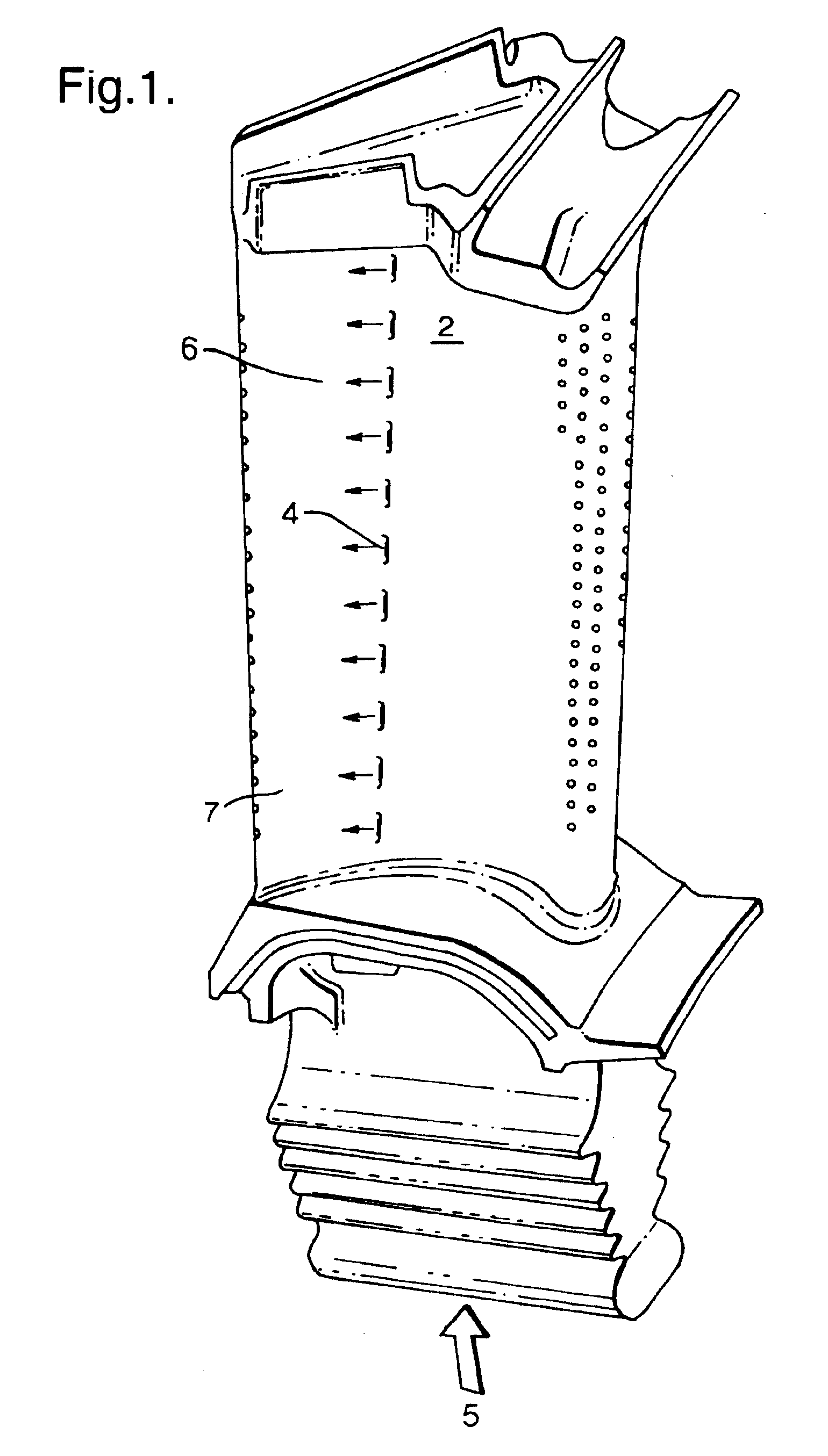
[0022]Referring now to FIG. 1 a gas turbine component 2 is shown. The component 2 is a nozzle guide vane used in a gas turbine engine, located in the hot gas path immediately downstream of the engine combustor (not shown). In order to operate in such a hostile environment the component 2 is provided with a number of thin film cooling holes 4. Cooling air 5, provided to an internal passage of the component exits through the cooling holes to form a thin cooling film 6 over an external first surface 7 of the component.

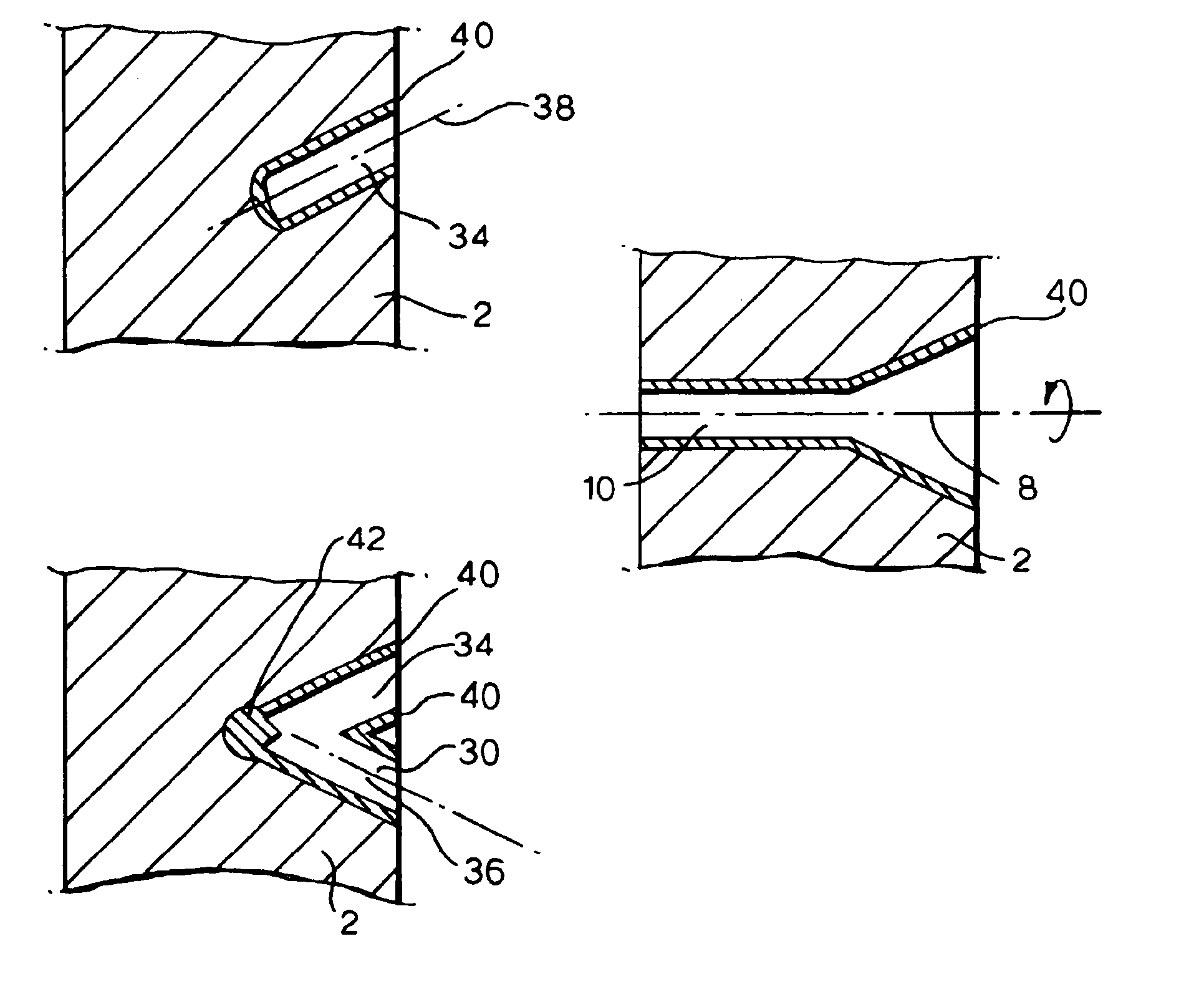
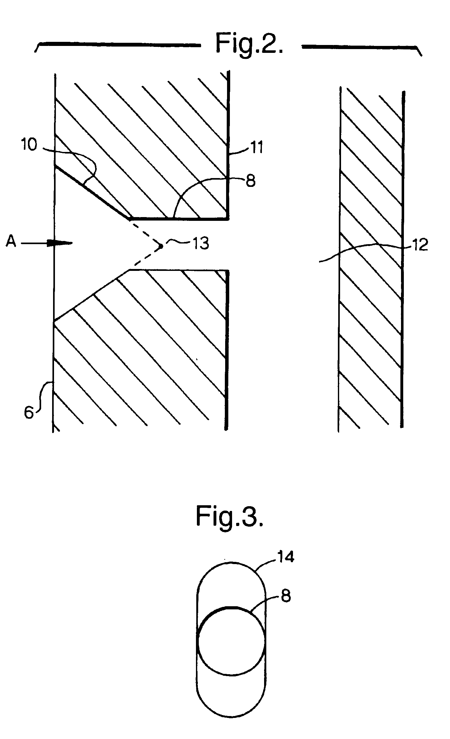
[0023]Referring now to FIG. 2 a cross section of a film cooling hole 4 is shown to illustrate the general construction of such a feature. The cooling hole 4 comprises a communicating passage 8 and a fan shaped cavity 10. The communicating passage 8, typically of constant bore, provides communication between an internal second surface II, bounding an internal passage 12 of the component, and the fan shaped cavity 10. The passage 8 is also called a controlling hole as it me...


PUM

PropertyMeasurementUnit
temperaturesaaaaaaaaaa
pressureaaaaaaaaaa
poweraaaaaaaaaa

Abstract

A method of manufacturing a through hole in a component between a first surface and a second surface, the through hole including a cavity formed in the first surface and a communicating passage between the second surface and the cavity including the steps of:a) laser percussion drilling a plurality of blind holes in the first surface to form the cavity andb) drilling a communicating passage between the cavity and the second surface.

Description

[0003]Continuation of U.S. application Ser. No. 10 / 283,146, filed Oct. 30, 2002, now U.S. Pat. No. 6,781,091.BACKGROUND OF THE INVENTION[0004]1. Field of Invention[0005]The present invention relates to a method of forming a shaped hole in a component. In particular the present invention relates to the laser drilling of a cooling hole in a component of a gas turbine engine.[0006]2. Description of Related Art[0007]Components in a gas turbine engine are often cooled to survive the high temperatures found therein. One method used is thin film cooling by a supply to air, used as a cooling fluid, is provided to a passage within the component, exiting via cooling holes to form a thin film over the external surface of the component. In addition to removing heat from the component by conduction, the thin film of cooling air serves to prevent hot gas within the gas turbine engine impinging upon the component.[0008]The cooling air used for thin film cooling must be supplied at a pressure great...

Claims


Application Information

Patent Timeline
Patent Type & Authority Patents(United States)
IPC IPC(8): B23K26/00B23K26/38F01D5/18
CPCB23K26/383B23K26/388F01D5/186F05D2230/13B23K26/384B23K26/389
Inventor BYRD, PAMELA JHASTILOW, NEIL KSTEVENS, MARTIN J
Owner ROLLS ROYCE PLC
Why Eureka
Try Eureka