Method and apparatus for slotting tubular steel

a tubular steel and slotting blade technology, applied in band saws, manufacturing tools, saw chains, etc., can solve the problems of not being able to effectively remove all wickers, no prior art has been identified which addresses chip clearing, and the control of the chip geometry and the chip-clearing ability of the slotting tool, etc., to achieve the effect of improving the geometry of the slotting blade and improving the slotting efficiency

Inactive Publication Date: 2010-06-03
NOETIC TECH INC
View PDF7 Cites 2 Cited by
  • Summary
  • Abstract
  • Description
  • Claims
  • Application Information

AI Technical Summary

Benefits of technology

[0011]The present invention provides methods and apparatus for achieving improved slotting blade geometry and improved slotting efficiency for purposes of forming slotted tubular steel liners, while at the same time allowing through-wall slots to be cut without producing “wickers” on the inside of the tubular where the slotting blade emerges through the wall of the tubular.
[0012]Accordingly, in a first aspect the present invention is a circular blade for cutting thin slots in tubular steel. As used in this patent specification, the term “thin slot” refers to slots having a width less than or equal to approximately 0.0625 inches). The blade is configured such that all chips produced during slotting operations will be narrower than the slot width. As a result of the novel geometry of the blade, clearance of chips from cut slots is facilitated, and loads acting on the blade during slotting operations are reduced, thus reducing blade wear and blade breakage as well as related repair and maintenance costs.
[0013]In a second aspect, the present invention is a method for cutting slots in tubular steel, comprising the steps of inserting an inflatable sacrificial liner into a section (or “joint”) of pipe to be slotted, pre-loading the sacrificial liner into substantially uniform contact against the inside surface of the pipe, and plunging one or more rotating circular slotting blades through the wall of the pipe and partially into the sacrificial liner. As the blades emerge through the inner face of the pipe wall, the liner prevents or deters the formation of wickers, and prevents cuttings and cutting fluid from entering the inside diameter of the pipe. The next step in the process is to remove the liner from the pipe, leaving a substantially wicker-free bore. In preferred embodiments of the method of the invention, the blades used in the slotting operation are configured in accordance with the aforesaid first aspect of the invention. Additional but non-essential steps in the method of the invention may include flushing the pipe (after slotting) with cutting fluid, wiping the slotted pipe as it leaves the slotting machine to keep the cuttings and the cutting fluid in the slotting machine where they can be handled efficiently, and washing the pipe to remove cutting fluid.

Problems solved by technology

From a machining standpoint, one difficulty in slotting operations arises in the control of the chip geometry and chip-clearing ability of the slotting tool (the phrase “chip geometry” being used herein with reference to the configuration of metal fragments formed during slotting operations).
However, no prior art has been identified which addresses chip clearing in the context of cutting very narrow slots as typically required for slotted well liners.
However, this type of device does not effectively remove all the wickers; instead, some wickers are bent into the slots from which they originated.
This acts to plug the slots, thus reducing the open area and reducing the effectiveness of the slotted liner.
This process can be less than optimally effective if the wickers are too large; in such cases, the heat transfer rate from the wicker to the pipe can be sufficiently large that the wickers cannot be brought to vaporization temperature without adversely affecting the properties of the base material.
This washing process flattens and bends wickers, further reducing the effectiveness of the vaporization process.
Both of the processes described above (Hara and Claerhout) involve extra process steps and are time and energy intensive.
This results in a significant amount of cutting fluid leaving the slotting machine from the machine's cutting fluid circulation system.
The cutting fluid can become contaminated once outside the slotting machine, in which case it must be replaced, or else captured during the washing process and treated for re-use.
Both of these options are expensive, and the treatment option risks reducing fluid quality.
Known slotting processes typically generate large volumes of cuttings.
These chips are very fine and cause wear in the pipe-handling equipment, and they present a safety hazard to personnel.
It is difficult and expensive to handle these chips outside of the slotting machines.

Method used


Image

  • Method and apparatus for slotting tubular steel
  • Method and apparatus for slotting tubular steel
  • Method and apparatus for slotting tubular steel

Examples


Embodiment Construction

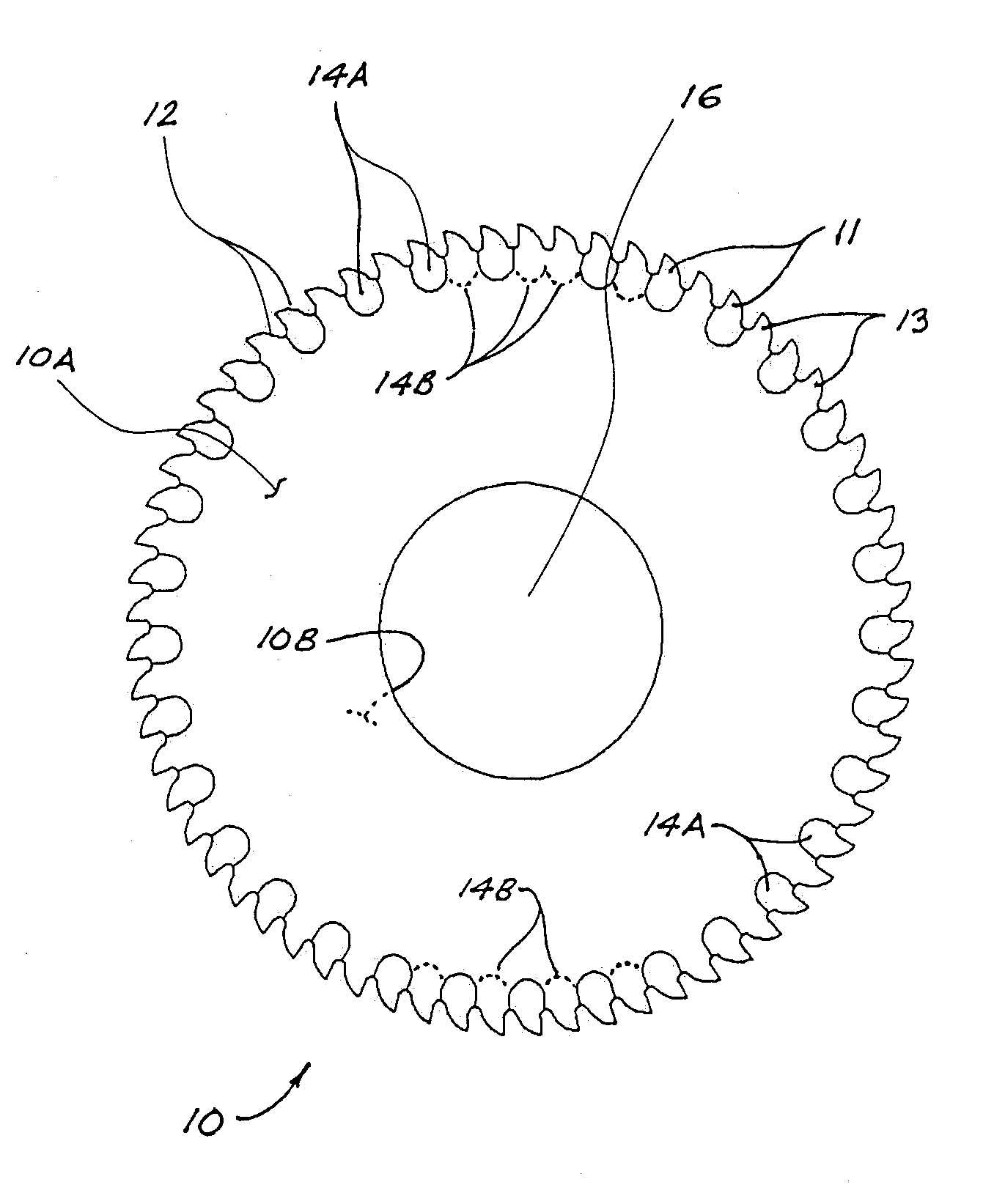
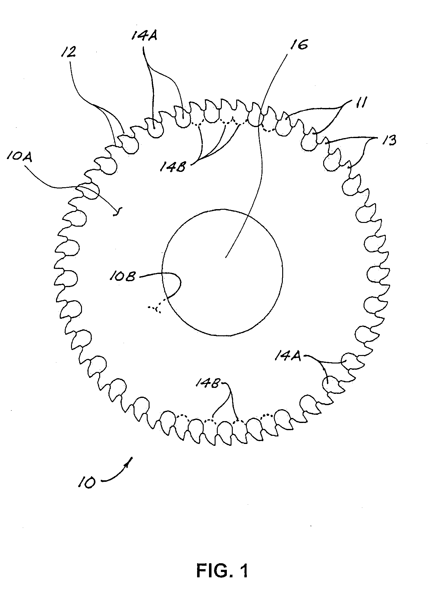
[0031]FIG. 1 illustrates an embodiment of a circular blade 10 in accordance with a first aspect of the present invention, particularly adapted for uses such as slotting tubular steel. Blade 10 has a central arbor opening 16, for mounting blade 10 on the rotatable arbor of a slotting machine, plus a plurality of generally curvilinear teeth 12 arrayed around the circumference of blade 10. Blade 10 has a first face 10A (shown in FIG. 1) and an opposite second face 10B. The thickness of teeth 12 is less than the thickness of blade 10, such that each tooth 12 has both an inner face 11 and an outer face 13, with each outer tooth face 13 being flush with either first face 10A or second face 10B of blade 10, and with outer tooth faces 13 being alternatingly flush with first face 10A and second face 10B from one tooth 12 to the next. This feature has the effect of reducing the width or thickness of metal chips or cuttings that teeth 12 cut from tubular steel workpieces (or other metal workpi...


PUM

PropertyMeasurementUnit
widthaaaaaaaaaa
thicknessesaaaaaaaaaa
widthaaaaaaaaaa

Abstract

In a method for slotting a pipe, a sacrificial liner is inserted into the pipe and radially expanded into contact against the inner pipe wall surface, where-upon rotating blades are plunged through the pipe wall and partially into the sacrificial liner. The sacrificial liner prevents the formation of wickers, and prevents cuttings and cutting fluid from entering the interior of the pipe, thus facilitating production of wicker-free slotted pipe requiring reduced post-slotting cleaning. An apparatus for implementing the method incorporates a fixed seal sub-assembly and a movable seal sub-assembly, interconnectable to form an elongate assembly which is adjustable to suit different pipe lengths. A cylindrical re-usable liner is disposable around the assembled fixed and movable seal sub-assemblies, and sized for insertion into the sacrificial liner. The re-usable liner may be expanded by internal pressure, thereby expanding the sacrificial liner. Preferably, the slotting method uses slotting blades with curvilinear teeth thinner than the main blade body, to produce cuttings that are narrower than the finished slot width, and therefore easier to remove from the slots during slotting operations.

Description

FIELD OF THE INVENTION[0001]The present invention relates in general to methods and apparatus for slotting ductile metal workpieces, including tubular steel workpieces to create slotted liners as typically used in heavy oil production from unconsolidated sand reservoirs. The invention relates in particular to methods and apparatus for slotting tubular steel whereby the formation of wickers during the slotting process may be substantially reduced or eliminated.BACKGROUND OF THE INVENTION[0002]Slotted steel pipe liners are commonly used for sand control in the oil and gas industry. Typically, slotted liners are formed by cutting multiple slots in the range of 2 to 4 inches long through the pipe wall, and parallel to the axis of the liner. The purpose of the slots is to provide a flow path for fluids (e.g., steam) to be injected into a subsurface formation, or for produced fluids (e.g., oil and natural gas) to flow from a subsurface formation into a well, while preventing the ingress o...

Claims


Application Information

Patent Timeline
Patent Type & Authority Applications(United States)
IPC IPC(8): B26D7/08B23D61/02B26D3/00
CPCB23D61/021B23D45/122Y10T83/0405Y10T83/0596Y10T83/9319
Inventor SLACK, MAURICE WILLIAMJANTZEN, LEON K.
Owner NOETIC TECH INC
Why Eureka
Try Eureka