Wall pipeline slotting machine

A slotting machine and pipeline technology, which is applied in construction, building construction, etc., can solve the problems of shallow pipeline groove depth, unstable equipment operation, high manufacturing cost, etc.

Active Publication Date: 2018-09-14
THE THIRD CONSTR ENG CO LTD OF CHINA CONSTR SECOND ENG BUREAU
View PDF2 Cites 4 Cited by
  • Summary
  • Abstract
  • Description
  • Claims
  • Application Information

AI Technical Summary

Problems solved by technology

Among them, the Chinese patent application number: 201110034679.2 provides the technical scheme of "Telescopic Dust-free Wall Grooving Machine" as follows: a slideway and a water spray atomization dust removal mechanism are provided on the mobile car body, and a slideway is provided on the slideway to move along the slideway. The sliding rod lifting mechanism, the upper end of the sliding rod lifting mechanism is provided with a slotting working part with a slotting blade. In this technical solution, the sliding rod lifting mechanism has a complex structure, difficult manufacturing and high manufacturing cost; in addition, because the slotting working part is located in the At the uppermost end of the entire slotting device, the moment arm formed between the action point of the blade and the support point of the equipment is the entire length of the entire structure. When slotting, the force couple formed by the reaction force of the wall to the slotting blade is always in the maximum state. This couple It will make the equipment work unstable, make the slotting device tilt or even fall over, so that the depth of the opened pipeline slot will gradually become shallower, and the expected effect will not be achieved.
Also have Chinese patent application number: 201520747594.2 provided " a kind of new type wall slotting machine " technical scheme is: comprise the mobile car body that has handlebar and the guide bar on the mobile car body, be installed on the guide bar by fixing bolt The main body of the slotting machine (that is, the slotting working part) has two handles on the main body of the slotting machine. The guide rod structure of this technical solution, in addition to the relatively complicated structure of the guide rod, also has relatively large defects in use. When grooving, loosen the fixing bolts of the slotting machine body fixed on the guide rod, hold the two handles of the slotting machine body with both hands, and manually move the slotting machine body up or down for slotting; using this slotting machine, Workers operate manually in the high dust state of environmental pollution, which is labor-intensive and endangers their health

Method used


Image

  • Wall pipeline slotting machine
  • Wall pipeline slotting machine
  • Wall pipeline slotting machine

Examples


Embodiment Construction

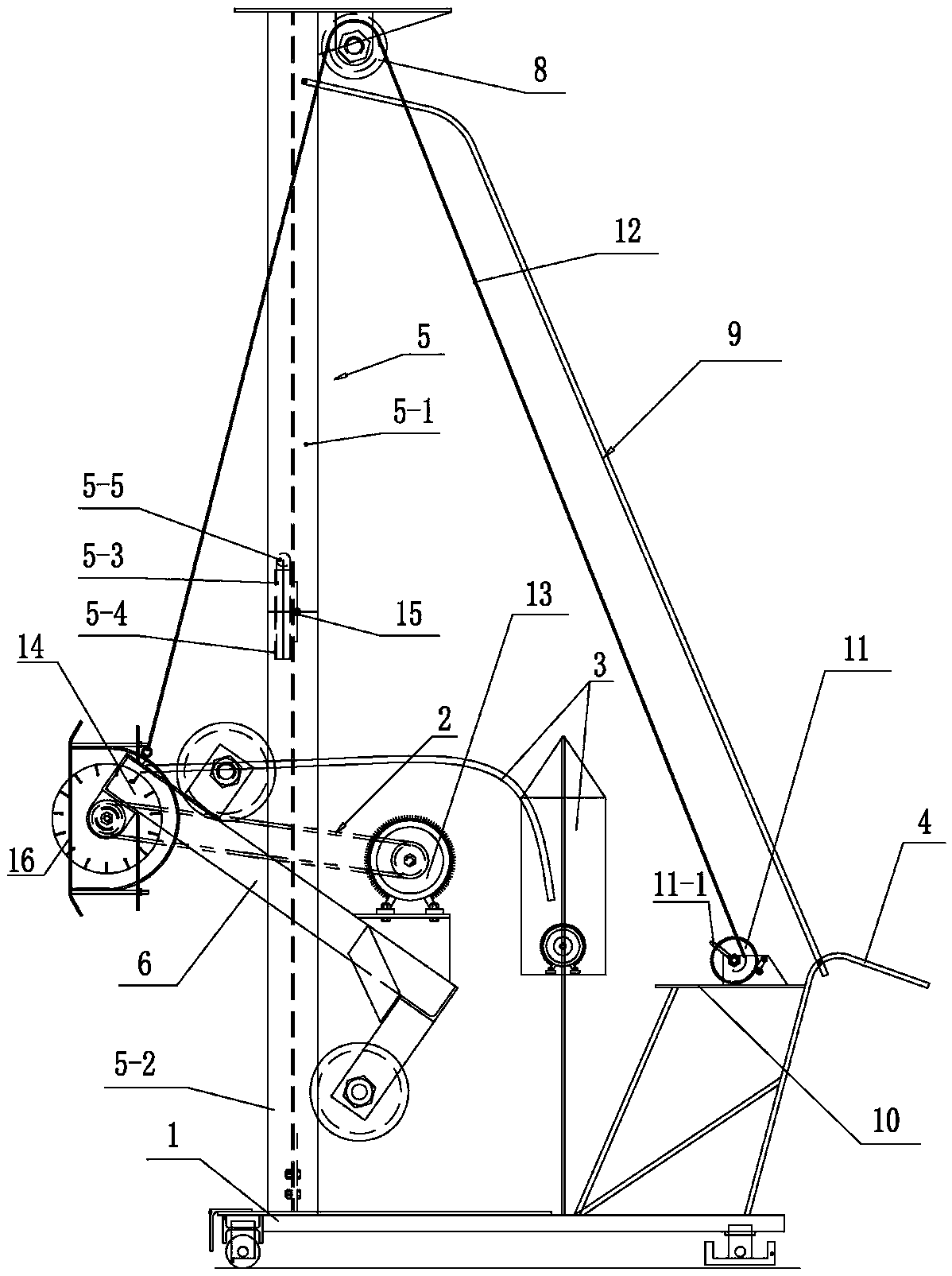
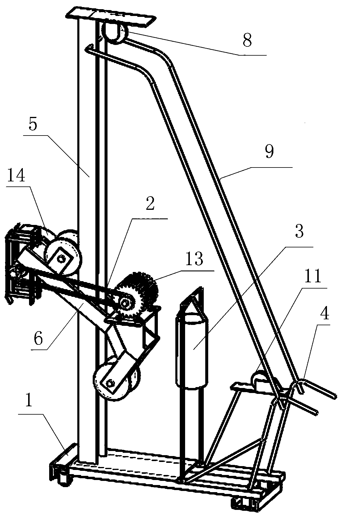
[0014] Such as figure 1 , image 3 As shown, the wall pipeline slotting machine of the present invention includes a mobile car body 1 with a handle 4, a slotting working part 2 driven by a motor 13 to drive a blade cutting mechanism 14 on the mobile car body 1, and a water spray dust removal device 3. Mobile car body 1 front part is provided with an I-beam climbing column 5, and I-beam climbing column 5 is provided with a crawling frame 6, and slotting work portion 2 is installed on the crawling frame 6. The top of the I-beam climbing column 5 is provided with a fixed pulley 8. The I-beam climbing column 5 is respectively hinged a support rod 9 at both sides of the fixed pulley 8 bottom, and the lower ends of the two support rods 9 are connected to the handlebar 4 both sides of the car body 1 rear portion respectively. An equipment and switch installation panel 10 is arranged between the handlebars 4 transversely. The equipment and switch installation panel 10 is provided w...


PUM


Abstract

The invention relates to a wall pipeline grooving machine which comprises a moving vehicle body, a grooving work part and a water spraying and dust removing device. The wall pipeline grooving machine further comprises a moving mechanism formed by an I-shaped steel climbing column, a climbing frame, a ratchet mechanism, a steel cable and a fixed pulley together. The grooving work part is mounted on the climbing frame, and the climbing frame can vertically move on the I-shaped steel climbing column through the traction of the ratchet mechanism and the steel cable. The I-shaped steel climbing column can be stretched or folded for use. The I-shaped steel climbing column is well fixed according to the floor height of a room, a switch on an equipment and switch mounting panel is turned on, the grooving work part works while the water spraying and dust removing device makes a wall body moist, the ratchet mechanism is operated to drive the climbing frame to move upwards along the I-shaped steel climbing column, and a blade of the grooving work part cuts along the wall body to carry out wall grooving operation under the situation of no environmental pollution. The wall pipeline grooving machine provided by the invention is reasonable in structure, stable in overall work, simple to operate, high in grooving efficiency, orderly and standard in grooving, straight and attractive in grooving, and consistent in groove depth; by using the wall pipeline grooving machine provided by the invention, both time and labor are saved, and the project progress is quick.

Description

technical field [0001] The invention relates to a mechanical slotting device, in particular to a wall pipeline slotting machine. Background technique [0002] In the prior art, there are many kinds of mechanical equipment for wall slotting. Among them, the Chinese patent application number: 201110034679.2 provides the technical scheme of "Telescopic Dust-free Wall Grooving Machine" as follows: a slideway and a water spray atomization dust removal mechanism are provided on the mobile car body, and a slideway is provided on the slideway to move along the slideway. The sliding rod lifting mechanism, the upper end of the sliding rod lifting mechanism is provided with a slotting working part with a slotting blade. In this technical solution, the sliding rod lifting mechanism has a complex structure, difficult manufacturing and high manufacturing cost; in addition, because the slotting working part is located in the At the uppermost end of the entire slotting device, the moment a...

Claims


Application Information

Patent Timeline
Patent Type & Authority Patents(China)
IPC IPC(8): E04F21/00
CPCE04F21/00
Inventor 王天东王冰飞杨发兵刘辉李军孟亮王鹏程徐小烈皮佳亮崔秀生李猛杨海龙
Owner THE THIRD CONSTR ENG CO LTD OF CHINA CONSTR SECOND ENG BUREAU
Why Eureka
Try Eureka