
System for selectively controlling spin-up control for data storage devices in an array using predetermined out of band (OOB) signals

a data storage device and array technology, applied in the field of data storage devices, can solve the problems of high cost of large capacity power supply, significant increase in the overall cost of the disc drive array, and related costs of extra cooling and space requirements, and achieve the effect of selective spin-up of the data storage devi

Inactive Publication Date: 2005-07-05
SEAGATE TECH LLC
View PDF9 Cites 50 Cited by
  • Summary
  • Abstract
  • Description
  • Claims
  • Application Information

AI Technical Summary

Benefits of technology

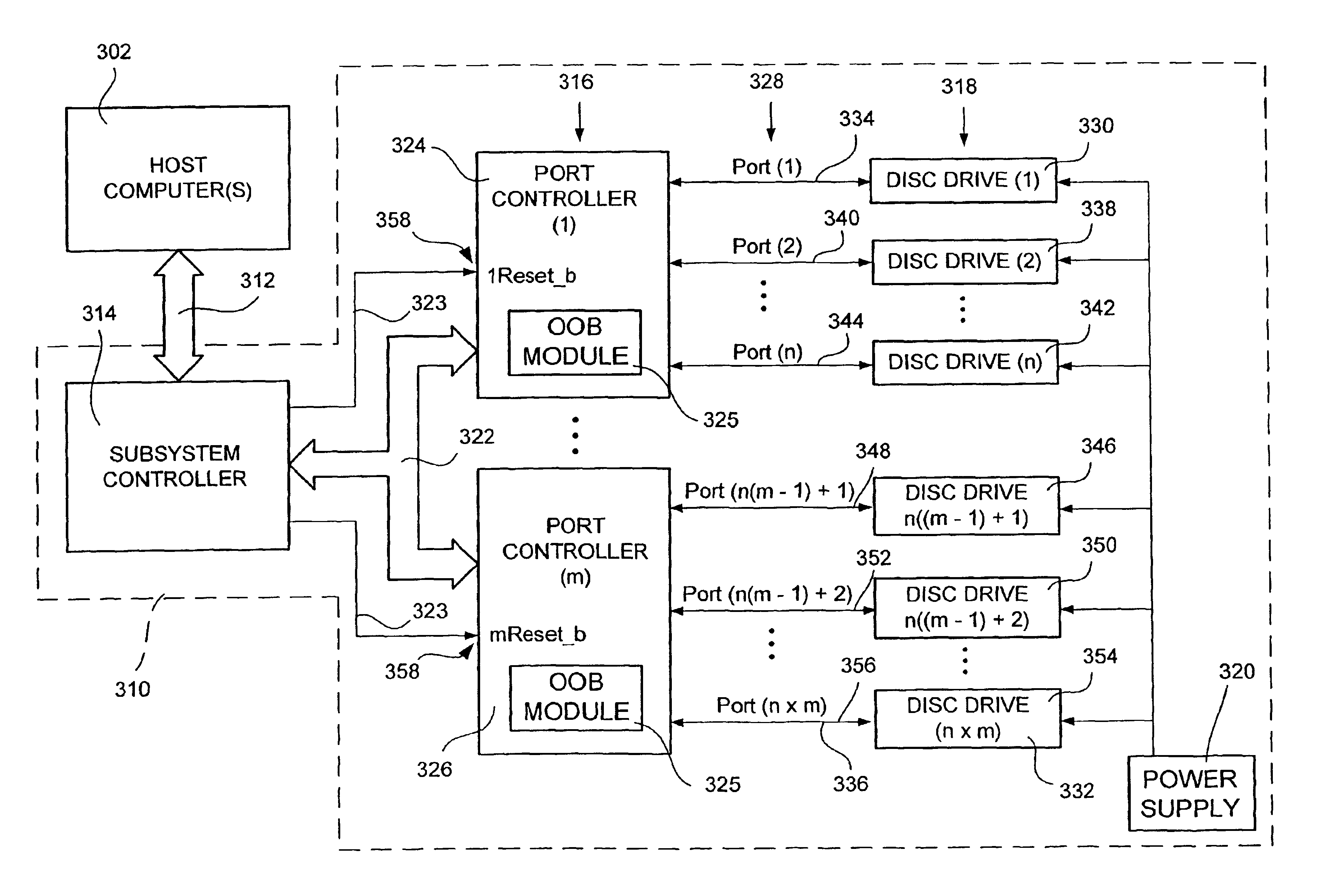
[0014]In accordance with one embodiment of the present invention, an array of data storage devices includes a timing controller, two or more port controllers, and a plurality of data storage devices, each of the data storage devices being associated with, and in communication with, one of the port controllers. Each of the data storage devices is operable to spin-up its spindle motor in response to the successful communication of predetermined OOB signals with its associated port controller. Additionally, each of the port controllers is operable to communicate the predetermined OOB signals to its associated data storage devices in response to a receipt of a start signal from the timing controller. By selectively sending start signals from the timing controller to the port controllers, and thus selectively causing the port controllers to communicate the predetermined OOB signals with their associated data storage device(s), the selective spin-up of the data storage devices may be achieved.

Problems solved by technology

However, such large capacity power supplies add significantly to the overall cost of the disc drive array.
In addition to the high cost of the large capacity power supply, there are also the related costs of extra cooling and space requirements in the disc drive array for the large capacity power supply, as well as greater overall energy use of a disc drive array so equipped.
Unfortunately, as a typical parallel-ATA channel may only accommodate a single pair of master / slave devices, the spin-up of only one disc drive per parallel-ATA channel may be delayed in this manner.
Unfortunately, SCSI disc drives are typically much more expensive that ATA disc drives.

Method used


Image

  • System for selectively controlling spin-up control for data storage devices in an array using predetermined out of band (OOB) signals
  • System for selectively controlling spin-up control for data storage devices in an array using predetermined out of band (OOB) signals
  • System for selectively controlling spin-up control for data storage devices in an array using predetermined out of band (OOB) signals

Examples


Embodiment Construction

[0021]In general, the present disclosure describes methods and systems for controlling spindle motor spin-up in an array of data storage devices. More particularly, the present disclosure describes methods and systems for accurately controlling the sequencing of spindle motor spin-up in an array of data storage devices using out-of-band signaling, so that an appropriate overall spindle motor startup load may be achieved for the array of data storage devices.

[0022]While the various embodiments of the present invention are described herein particularly with respect to disc drives and disc drive arrays, it will be understood to those skilled in the art that the methods and systems described herein are applicable to spin-up sequencing control in other types of data storage devices and data storage device arrays.

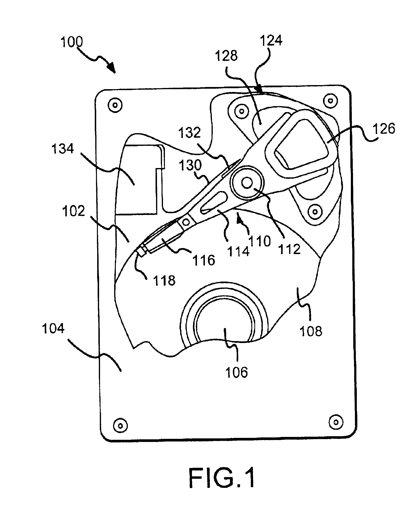
[0023]An exemplary disc drive 100 in which embodiments of the present invention may be incorporated is shown in FIG. 1. The disc drive 100 includes a base 102 to which various co...


PUM


Abstract

A data storage device array includes a number of data storage devices. Each of the disc drives is operable to spin-up its spindle motor in response to the successful communication of predetermined out-of-band (OOB) signals. By selectively causing the communication of the predetermined OOB signals to the data storage devices, the selective spin-up of the data storage devices may be achieved.

Description

RELATED APPLICATIONS[0001]This application claims priority of U.S. Provisional Application Ser. No. 60 / 341,321, filed Dec. 13, 2001.FIELD OF THE INVENTION[0002]This application relates generally to data storage devices and more particularly to the sequencing of spindle motor spin-up in an array of data storage devices.BACKGROUND OF THE INVENTION[0003]Disc drives are digital data storage devices that enable users of computer systems to store and retrieve large amounts of data in a fast and efficient manner. Disc drives of the present generation have data storage capacities in excess of tens of gigabytes (GB) and can transfer data at sustained rates of several megabytes (MB) per second.[0004]A typical disc drive includes a plurality of magnetic recording discs which are mounted to a rotating hub of a spindle motor for rotation at a constant, high speed. An array of read / write heads are disposed on adjacent surfaces of the discs to transfer data between the discs and a host computer. T...

Claims


Application Information

Patent Timeline
IPC IPC(8): G11B19/20
CPCG11B19/20
Inventor WOOD, ROBERT BARRYPRIBORSKY, ANTHONY LEIGHDIXON, ROBERT WILLIAM
Owner SEAGATE TECH LLC
Learn More