Methods of utilizing noise cores in PLD designs to facilitate future design modifications

Active Publication Date: 2005-07-05
XILINX INC
View PDF9 Cites 21 Cited by
  • Summary
  • Abstract
  • Description
  • Claims
  • Application Information

AI Technical Summary

Benefits of technology

[0019]In some embodiments, repeating the setting and testing comprises gradually incr

Problems solved by technology

As PLD designs increase in complexity, they reach a point at which the designer cannot deal with the entire design at the gate level.
However, additional issues remain.
One issue that can sometimes be a design challenge is the provision for alterations in a design at a future time.
For example, design changes can be necessitated by errors in the or

Method used


Image

  • Methods of utilizing noise cores in PLD designs to facilitate future design modifications
  • Methods of utilizing noise cores in PLD designs to facilitate future design modifications
  • Methods of utilizing noise cores in PLD designs to facilitate future design modifications

Examples


Example

DETAILED DESCRIPTION OF THE DRAWINGS

[0032]In the following description, numerous specific details are set forth to provide a more thorough understanding of the present invention. However, it will be apparent to one skilled in the art that the present invention can be practiced without these specific details.

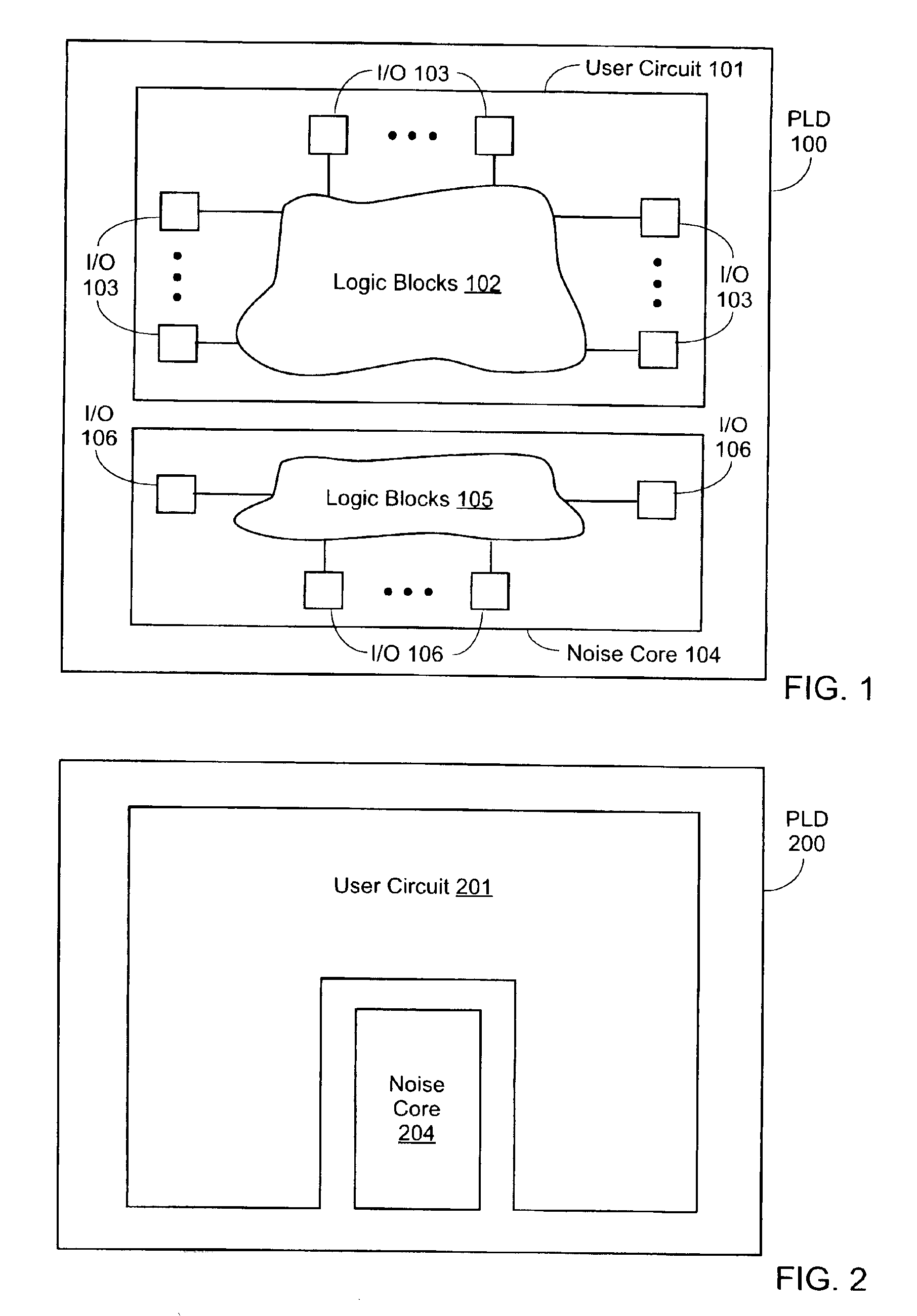
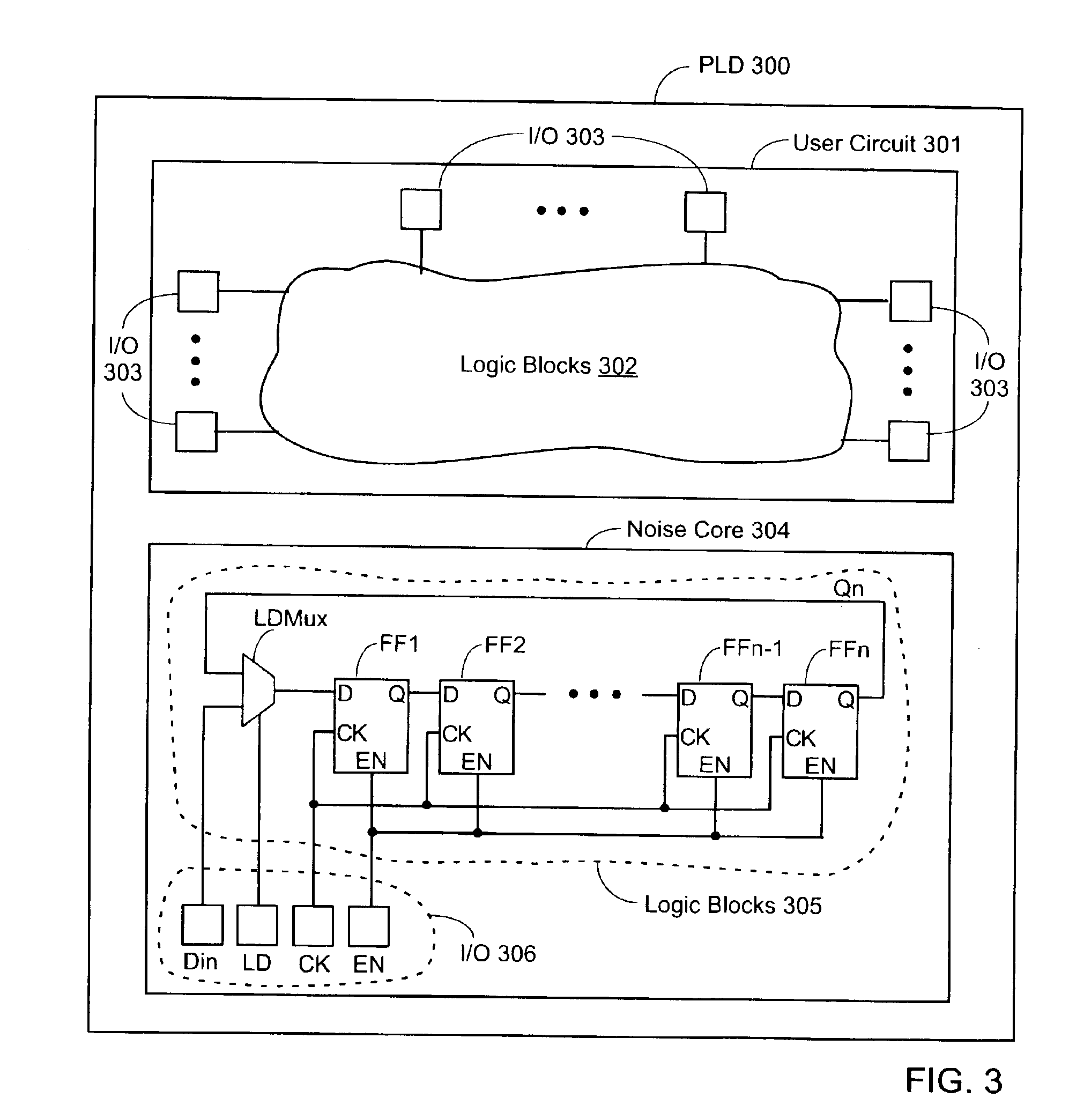
[0033]FIG. 1 shows a PLD 100 in which a noise core 104 is implemented along with a user circuit 101. User circuit 101 typically includes a number of logic blocks 102 and several input / output (I / O) blocks 103. Noise core 104 also includes one or more logic blocks 105 and accompanying I / O pad(s) 106.

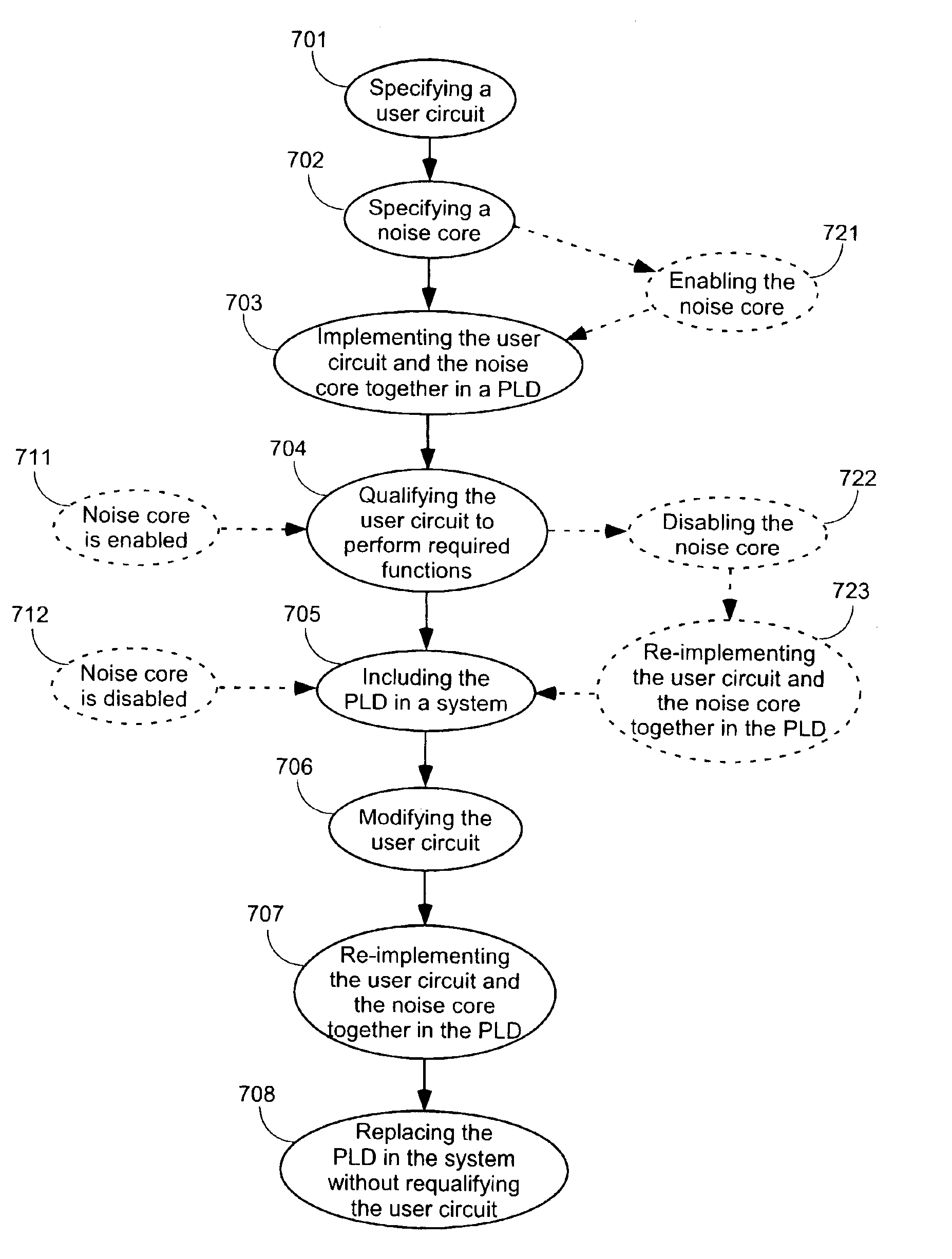
[0034]The user circuit and the noise core can be implemented in separate areas of the PLD, as shown in FIG. 1. However, if modifications are later made to the user circuit, the modifications might be made to logic embedded in the interior of the user circuit. Therefore, to emulate the noise level that might be created by later additions or changes to the circuit, it can be preferable to...


PUM


Abstract

Methods of using “noise cores” in a PLD design. “Noise cores” are pre-developed blocks of logic included in a PLD design for the purpose of creating noise in other circuits also implemented in the PLD. By gradually increasing the level of noise created by the noise core, the noise sensitivity of the user circuit can be determined. Also, by ensuring that the user circuit functions properly when combined with the noise core, a designer can have confidence that unmodified portions of the user circuit will still function properly when the user circuit is modified. In some embodiments, once the user circuit has been qualified with the noise core operational, the noise core is disabled prior to including the PLD design in a system. Because the user circuit is proven to withstand a certain level of noise, future additions to the design do not necessarily require re-qualification of the user circuit.

Description

FIELD OF THE INVENTION[0001]The invention relates to programmable logic devices (PLDs). More particularly, the invention relates to cores for a PLD designed for the purpose of creating noise in other circuits implemented in the PLD with the cores, and methods of utilizing such cores to facilitate future design modifications.BACKGROUND OF THE INVENTION[0002]Programmable logic devices (PLDS) are a well-known type of digital integrated circuit that can be programmed to perform specified logic functions. One type of PLD, the field programmable gate array (FPGA), typically includes an array of configurable logic blocks (CLBs) and programmable input / output blocks (IOBs). The CLBs and IOBs are interconnected by a programmable interconnect structure. Some FPGAs also include additional logic blocks with special purposes (e.g., DLLS, RAM, and so forth).[0003]The CLBs, IOBs, interconnect, and other logic blocks are typically programmed by loading a stream of configuration data into internal co...

Claims


Application Information

Patent Timeline
IPC IPC(8): G06F17/50G01R31/3185
CPCG01R31/318516G06F17/5054G06F30/34
Inventor LESEA, AUSTIN H.
Owner XILINX INC
Why Eureka
Try Eureka