Milliwave transmitting device, milliwave receiving device and milliwave transmission and reception system capable of simplifying wiring of a receiving system of terrestrial broadcasting service and satellite broadcasting service

Inactive Publication Date: 2005-07-05
SHARP KK
View PDF32 Cites 202 Cited by
  • Summary
  • Abstract
  • Description
  • Claims
  • Application Information

AI Technical Summary

Benefits of technology

[0019]Another advantage of the invention is that transmission and reception can be provided from a single transmitting device to a plurality of receiving devices.
[0020]The foregoing and other objects, fe

Problems solved by technology

In individual houses, however, transmission to a pl

Method used


Image

  • Milliwave transmitting device, milliwave receiving device and milliwave transmission and reception system capable of simplifying wiring of a receiving system of terrestrial broadcasting service and satellite broadcasting service
  • Milliwave transmitting device, milliwave receiving device and milliwave transmission and reception system capable of simplifying wiring of a receiving system of terrestrial broadcasting service and satellite broadcasting service
  • Milliwave transmitting device, milliwave receiving device and milliwave transmission and reception system capable of simplifying wiring of a receiving system of terrestrial broadcasting service and satellite broadcasting service

Examples


first embodiment

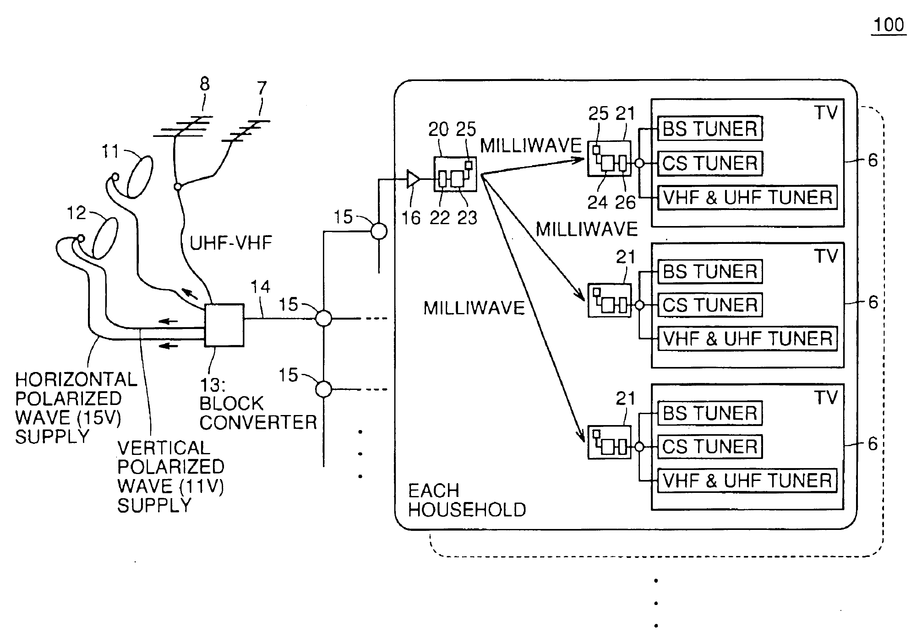
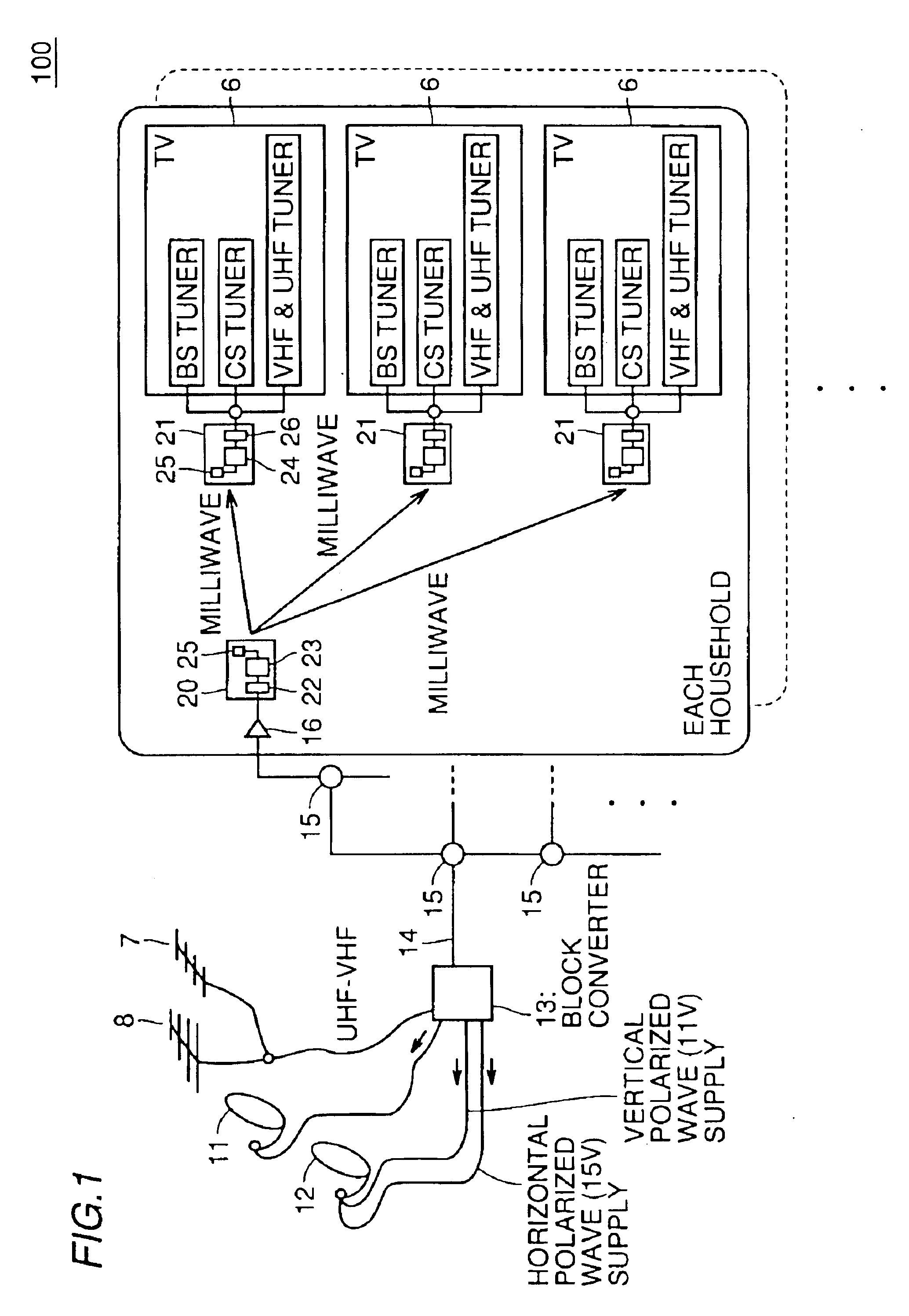
[0038]FIG. 1 shows a milliwave, wireless-transmission, TV receiving system 100 in a community house in accordance with a first embodiment of the invention. The identical and similar portions to those of the FIGS. 17 and 18 conventional examples are denoted by same reference characters.

[0039]Milliwave, wireless-transmission, TV receiving system 100 employs a milliwave of a frequency band of 60 GHz for the indoor, wireless system. A milliwave of the 60 GHz band is significantly higher in frequency and allows a radio-wave bandwidth of a transmitter and receiver to be wider than currently used-satellite and terrestrial TV broadcast waves so that terrestrial broadcasting service and satellite broadcasting service can be collectively radio-transmitted at one time. In addition, in this frequency band radiowaves are significantly absorbed by oxygen and water and thus readily blocked between adjacent houses. This frequency band is also suitable for wireless indoor transmission in a household...

second embodiment

[0053]FIG. 4 illustrates a configuration of an indoor, milliwave, wireless-transmission, TV receiving system 200 for an individual house in accordance with a second embodiment.

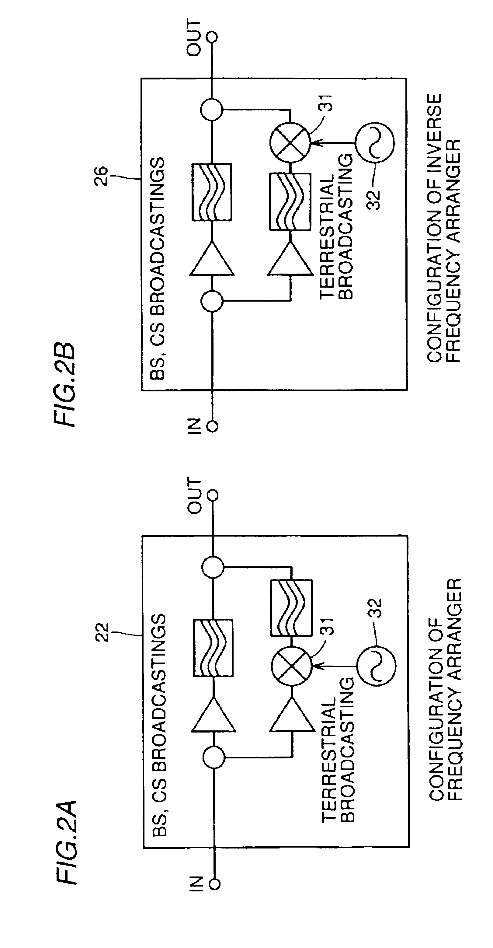
[0054]FIGS. 5A and 5B show a configuration of frequency arranger 22 and that of inverse frequency arranger 23, respectively, of milliwave, wireless-transmission, TV receiving system 200 in the second embodiment.

[0055]FIGS. 6A-6C show frequency arrangements when milliwave, wireless-transmission, TV receiving system 200 is used.

[0056]Hereinafter, the identical and similar portions to those shown in FIG. 1 are denoted by same reference characters and different portions are only described. Reference will now be made to FIG. 4 to FIGS. 6A-6C to describe a configuration and operation of milliwave, wireless-transmission, TV receiving system 200.

[0057]FIG. 4 shows transmission from a single milliwave transmitting device 20 to a plurality of milliwave receiving devices 21 (two milliwave receiving devices 21 in the pres...

third embodiment

[0066]FIG. 7 shows a second, indoor, milliwave, wireless-transmission, TV receiving system in an individual house. Hereinafter, the identical and similar portions to those shown in the FIG. 4 second embodiment are denoted by same reference characters and description is only provided for the different portions.

[0067]FIG. 7 shows transmission from a single milliwave transmitting device 20 to a plurality of milliwave receiving devices 21 (two milliwave receiving devices 21 in this embodiment). Milliwave transmitting device 20 and milliwave receiving device 21 are basically similar in configuration to those of the second embodiment shown in FIG. 4, except that the infrared signal converted from DC control bias 44 serving as the polarized-wave control signal for switching between vertical and horizontal polarized-wave components is substituted by an electronic-wave signal of a UHF band and that milliwave transmitting device 20 and milliwave receiving device 21 are respectively provided w...


PUM


Abstract

In conventionally receiving satellite broadcasting (BS, CS) and terrestrial broadcasting (VHF, UHF) services, transmitting the services to a plurality of TV receivers in an individual house results in complicated wiring and a community house is also limited in the number of installed TV receivers due to previously setting a distributor and thus requires an additional distributor to be installed when a TV receiver is additionally installed. The milliwave receiving and transmitting system of the present invention allows a broadcast signal to be transmitted and received indoors via indoor, wireless milliwave transmission without using any indoor wiring.

Description

BACKGROUND OF THE INVENTION[0001]1. Field of the Invention[0002]The invention relates to a milliwave transmitting device, milliwave receiving device, milliwave transmission and reception system and electrical appliance for indoor, wireless, milliwave transmission of a plurality of broadcast waves e.g. of terrestrial broadcasting service including VHF broadcasting, UHF broadcasting and the like, and satellite broadcasting service including BS (Broadcasting Satellite) broadcasting, CS (Communication Satellite) broadcasting and the like.[0003]2. Description of the Background Art[0004]Currently there have been implemented TV broadcasting in a plurality of electronic-wave bands, such as terrestrial broadcasting service (VHF, UHF), satellite broadcasting service (BS, CS) and the like.[0005]FIG. 17 shows a conventional configuration of a TV broadcast receiving system 900 in an individual house.[0006]For satellite broadcasting service, TV broadcast receiving system 900 receives a signal of ...

Claims


Application Information

Patent Timeline
IPC IPC(8): H04H1/00H04N7/10H04H1/02H04N7/20H04B1/16H04B1/26H04B7/00H04H20/63H04H40/90H04H60/90H04N5/00H04N21/414H04N21/61H04N21/647
CPCH04H20/63H04H40/90H04H60/90H04N7/106H04N7/20
Inventor SUEMATSU, EIJISATO, HIROYA
Owner SHARP KK
Why Eureka
Try Eureka