Cycle foot peg assembly

a technology for bicycles and components, applied in the field of bicycle foot assemblies, can solve the problems of vibration, shock, or torque, and the risk of accident to a cycle, and reduce the risk of injury to the cyclist, so as to reduce the chance of accident, improve safety, and contribute to the aesthetics of the motorcycle

Inactive Publication Date: 2005-07-12
ELLIOTT PIERRE J
View PDF8 Cites 9 Cited by
  • Summary
  • Abstract
  • Description
  • Claims
  • Application Information

AI Technical Summary

Benefits of technology

[0008]It is an object of the present invention to provide an improved cycle foot peg assembly which will afford to a rider reduced chance of accident and, thereby, greater safety in the event of inadvertent contact between the outermost edge of the foot peg assembly and ground or road into which it may come in contact.
[0009]It is another object to provide a foot peg assembly of the above type which is compatible with known and existing types of foot peg assemblies of cycles of all types, and which provides protection to the foot peg assembly if he cycle topples over.
[0010]It is a still further object to provide a foot peg assembly which also contributes to the aesthetics of the motorcycle and provides a potential for color coordination with colors associated with the painting and upholstery of the motorcycle proper.
[0011]It is a further object to provide a foot peg assembly of the above type which will provide for enhanced visibility of the cycle from the front and rear thereof.

Problems solved by technology

As such, any event which interferes with the normal shifting of weight or center of gravity of the rider relative to the cycle during such turning or traversing of uneven terrain can induce a vibration, shock, or torque to the foot peg assembly and, thereby, to the cycle frame and cycle itself in which a potentially disastrous result can occur if the end of the foot peg engages the road or terrain beneath the cycle.
However, neither this art, nor any other known to the inventor, has considered, or in anyway addressed a means by which the risk of accident to a cycle and injury to the cyclist may be diminished in the event of contact between the outer or distal-most end of the foot peg assembly and the earth or road therebeneath.

Method used


Image

  • Cycle foot peg assembly
  • Cycle foot peg assembly
  • Cycle foot peg assembly

Examples


Embodiment Construction

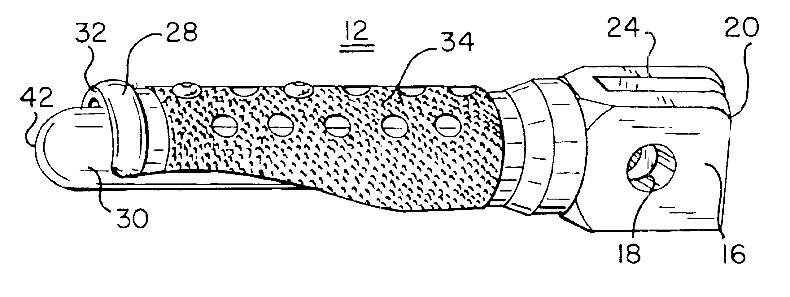
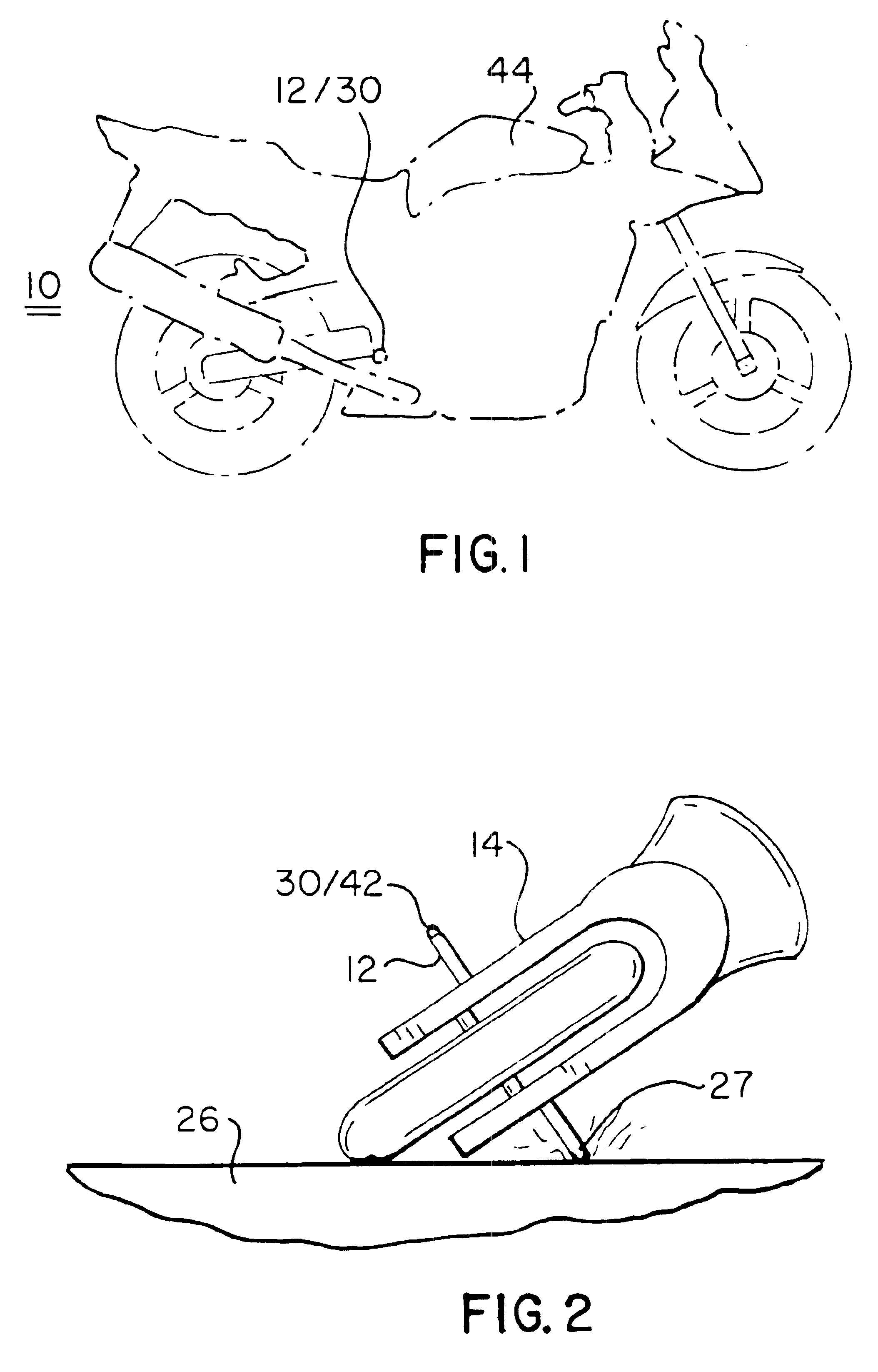
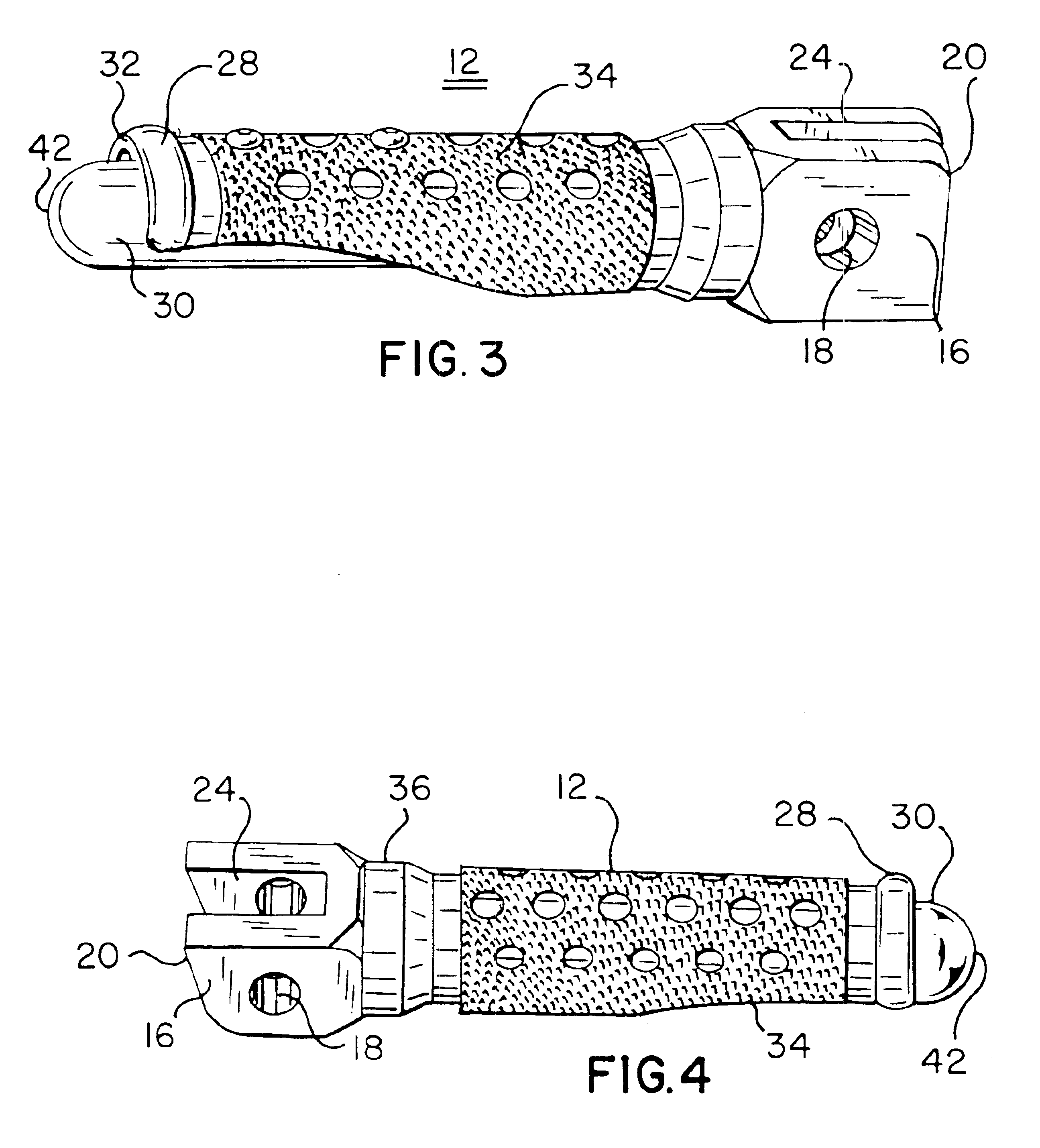
[0020]With reference to the phantom view of FIG. 1, a sport cycle 10 in accordance with the present invention may be seen to include many standard features, these including, without limitation, a foot peg assembly 12. Such assemblies are typically secured to a frame 14 (see FIG. 2) of the cycle through an end flange 16 (see FIG. 3) of the foot peg assembly and a bolt (not shown) which is positioned within a channel 18 within a proximal end 20 of the foot peg assembly 12. The structure of proximal end 20 is such that it includes a solid substantially rectangular open region 24 through which said channel 18 transversely passes. Such a connection to cycle frame 14 enables the foot peg assembly to be selectably flipped upward and, thereby, away from the legs of the rider when he does not wish to make use of the foot peg assembly.

[0021]As may be noted in FIG. 2, the need for the instant invention arises from the propensity of cycle riders to navigate their bikes in a fashion which gives ...


PUM


Abstract

The instant invention relates to a cycle foot peg assembly for engagement with the boot of a rider thereof. The assembly includes a foot peg housing comprising a proximal end and an open distal end, the proximal end including means for rigid connection to a frame of the cycle; and an elongate segment integrally between the proximal and distal ends, the segment including a bore therein having a longitudinal axis co-linear with a longitudinal axis of the foot peg housing, the bore in communication with the open distal end thereof. The assembly further includes a foot peg defining a greater longitudinal length than the axis of the bore of the elongate segment, the foot peg proportioned for complemental securable engagement within the bore, the peg further comprising a substantially hemispherical distal end, protruding beyond the open distal end of the foot peg housing, to a greatest axial dimension in a range of about 7.5 to about 15 millimeters.

Description

BACKGROUND OF THE INVENTION[0001]1. Field of Invention[0002]This invention relates to an invention in a cycle foot assembly of a type typically mounted upon motorcycles of various types.[0003]2. Prior Art[0004]Motorcycle riding and racing involves the use of the motorcycle on terrain which may be rough or uneven and, as well, often involves the navigation of sharp turns which may take the foot pedals, also termed foot pegs or foot peg assemblies, of the cycle close to, or in contact with, the road or ground itself. Distribution of the rider's weight is an important factor in balance of the cycle in that the weight of the rider will shift from side-to-side as he maneuvers through curves and / or over bumps in the terrain. As such, any event which interferes with the normal shifting of weight or center of gravity of the rider relative to the cycle during such turning or traversing of uneven terrain can induce a vibration, shock, or torque to the foot peg assembly and, thereby, to the cy...

Claims


Application Information

Patent Timeline
Patent Type & Authority Patents(United States)
IPC IPC(8): B62J25/00
CPCB62J25/00B62J25/06
Inventor ELLIOTT, PIERRE J.
Owner ELLIOTT PIERRE J
Why Eureka
Try Eureka