Armrest apparatus

Active Publication Date: 2005-07-12
NHK SPRING CO LTD
View PDF6 Cites 45 Cited by
  • Summary
  • Abstract
  • Description
  • Claims
  • Application Information

AI Technical Summary

Benefits of technology

[0012]This invention has been made in order to solve the above problems, and an object of the present invention is to provide an armrest apparatus in which by using a simple mechanism, the precision of par

Problems solved by technology

Because the locking operation as using the armrest and the lock-canceling operation as adjusting the armrest angle are effected by using the interlock member 140, the operation is cumbersome.
And besides, there is a possibility that upon inadvertently touching the interlocking member 140, the locking is accidentally cancelled, thus leading to

Method used


Image

  • Armrest apparatus
  • Armrest apparatus
  • Armrest apparatus

Examples


Embodiment Construction

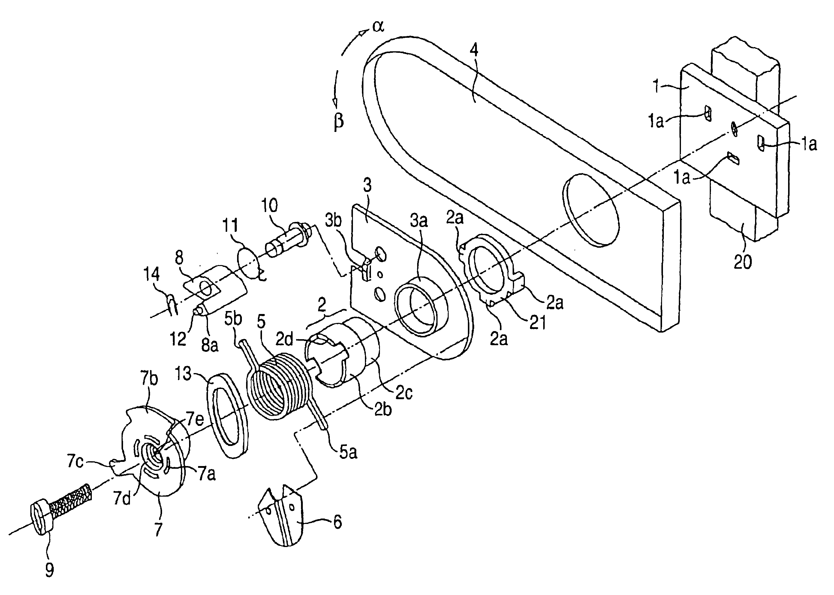
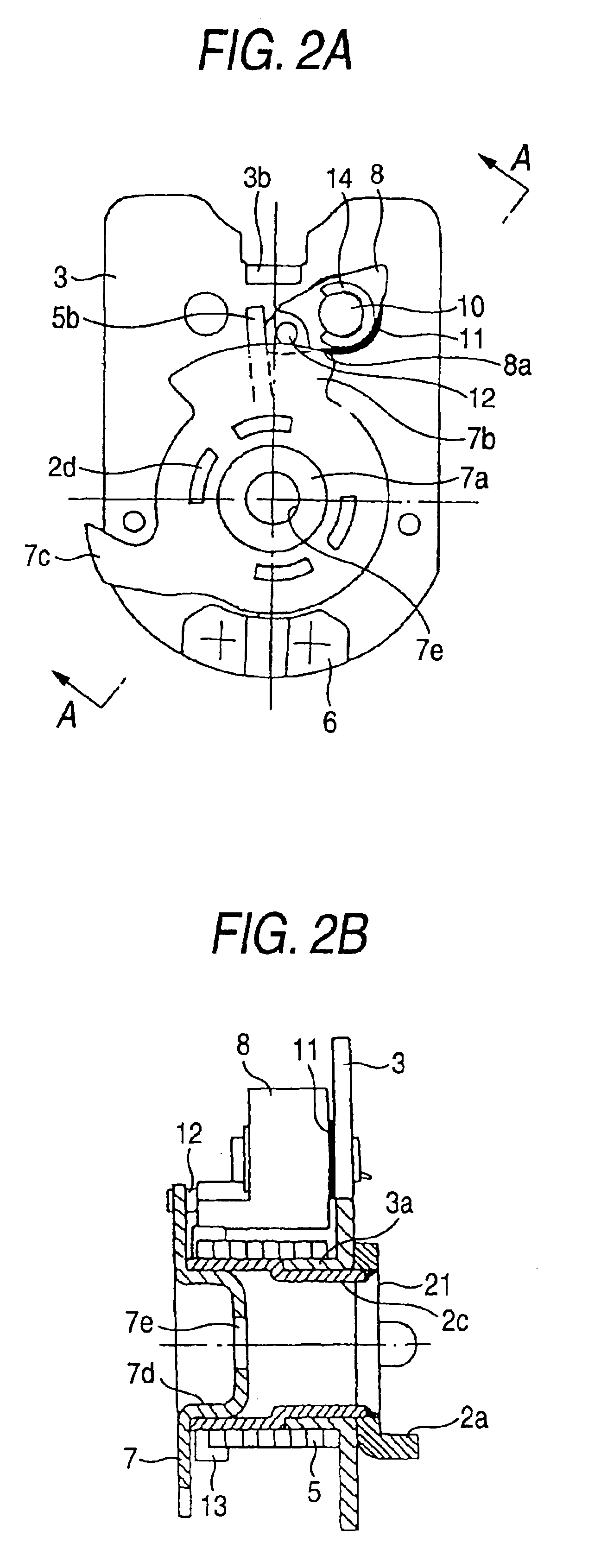
[0024]FIG. 1 is an exploded, perspective view of one preferred embodiment of an armrest apparatus of the present invention, FIG. 2A is a front-elevational view of the armrest apparatus in its assembled condition, and FIG. 2B is a side-elevational view (partly cross-sectional view) of the armrest apparatus of FIG. 2A.

[0025]The armrest apparatus of this embodiment comprises an armrest body 4, a rotation plate 3, a fixed shaft 2, a lock spring 5, a cam member 7, and a cancellation block 8. The whole of the armrest apparatus is mounted on an armrest mounting portion 1 fixedly secured by welding or the like to a seat frame 20.

[0026]The fixed shaft 2 has a stepped configuration, and has a larger-diameter portion 2b and a smaller-diameter portion 2c. A ring member 21 is fixedly secured by welding or the like to a distal end (directed toward the armrest mounting portion 1) of the smaller-diameter portion 2c. Therefore, the whole of the fixed shaft 2 is formed by integrally connecting the ri...


PUM


Abstract

An armrest apparatus includes a fixed shaft fixed to a seat frame, a rotation plate integrally connected to an armrest body and having a tubular portion into which the fixed shaft is inserted, a lock spring wound tightly on outer peripheral surfaces of a part of the fixed shaft and the tubular portion of the rotation plate in a free condition, a cancellation block rotatably mounted on a pivot shaft, and a cam unit mounted on a distal end of the fixed shaft and including a lock-canceling cam portion and a re-lock cam portion, the re-lock cam portion being spaced from the lock-canceling cam portion in a direction of rotation of the cam member.

Description

[0001]This application claims priority from Japanese Patent Application No. 2002-314897, filed Oct. 29, 2002, the entire contents of which are herein incorporated by reference to the extent allowed by law.BACKGROUND OF THE INVENTION[0002]1. Field of the Invention[0003]This invention relates to a movable-type armrest apparatus capable of adjusting the angle of an armrest of a seat in a step-less manner.[0004]2. Description of the Related Art[0005]An armrest on a seat of a vehicle or the like, when not in use, is held in a stored position (closed position) immediately adjacent to a backrest so that it will not become a hindrance.[0006]As shown in FIG. 4, one conventional armrest apparatus includes a shaft lock coil spring 120, and an operating mechanism 150 mounted on an armrest body 110 (see, for example, JP-Y-63-12773). This coil spring 120 is wound tightly on outer peripheral surfaces of the fixed shaft (not shown) fixed to a seat frame 100 side and rotation tube(not shown) (which ...

Claims


Application Information

Patent Timeline
IPC IPC(8): A47C7/54A47C1/03A47C1/022B60N2/46B60N2/75
CPCA47C1/03A47C7/54A47C7/543B60N2/4606B60N2/4633B60N2/753B60N2/767
Inventor KITAMURA, YOSHIHARUSAITO, MAKOTOOGINO, TAKASHIMIGITA, TOSHIYANAKAGAKI, YOSHIHISAWAKABAYASHI, NOBUYUKI
Owner NHK SPRING CO LTD
Why Eureka
Try Eureka