
Lens unit and camera module for endoscope

a technology of endoscope and lens unit, which is applied in the direction of optical elements, instruments, television systems, etc., can solve the problems of low operability the precision of the contact surface of the lens moving device movable in the optical axis direction inside the housing, and the precision of the lens moving device that cannot move easily, so as to achieve efficient production and raise the yield of the assembly of parts , the effect of raising the precision of the parts

Inactive Publication Date: 2013-04-04
FUJIFILM CORP
View PDF23 Cites 6 Cited by
  • Summary
  • Abstract
  • Description
  • Claims
  • Application Information

AI Technical Summary

Benefits of technology

The present invention aims to provide a lens unit and camera module for endoscope with precise sizes and efficient production. The lens holder holds the movable lens and a support device projects from it, while an anti-scatter device prevents light scattering and an aperture stop plate limits the light flux. The invention also includes a housing with a channel surface formed by machining, which raises the precision of the parts to be assembled. Overall, the invention improves the performance of the lens unit and camera module for endoscope.

Problems solved by technology

Precision of sizes of the relevant parts is an important problem irrespective of selection of the driving method, as the camera module has such a small size as 7×4×15 mm.
Specifically in the cam shaft type, a problem arises in precision of contact surfaces of the lens moving device movable in the optical axis direction inside a housing.
If a space between the lens moving device and guide surfaces of the housing is small, the lens moving device will not move readily with low operability.
However, it is very difficult to incorporate a motor in the head assembly of the elongated tube for rotating the cam shaft, because the camera module for the endoscope is characterized today in that a diameter of the elongated tube is preferably decreased for reducing physical stress to the body.
In the structure where the motor is incorporated in a proximal handle and a wire transmits torque of the motor to the cam shaft, it is impossible sufficiently to transmit the torque to the cam shaft.
Failure in the movement of the lens moving device occurs particularly if a space between the lens moving device and the guide surfaces is small.
If a space between the lens moving device and the guide surfaces is enlarged in view of higher operability, the movable lens / lens group is very likely to shake, to cause image blur within an image frame in the course of variable magnification.
It is difficult to drive the movable lens / lens group at a low torque because the movable lens / lens group moves with an inclination due to the shake.
It will be impossible to move the lens moving device mechanically according to the seriousness of the problem.
This is a complicated production which causes a drop of the yield of production seriously, or a proportion of the number of the accepted products per the number of the created products.
There arises a problem of creating unevenness in the precision of the sizes due to the black dyeing, which has been found by reconsidering relevant elements and their features in connection with the suitable precision.

Method used


Image

  • Lens unit and camera module for endoscope
  • Lens unit and camera module for endoscope
  • Lens unit and camera module for endoscope

Examples


Embodiment Construction

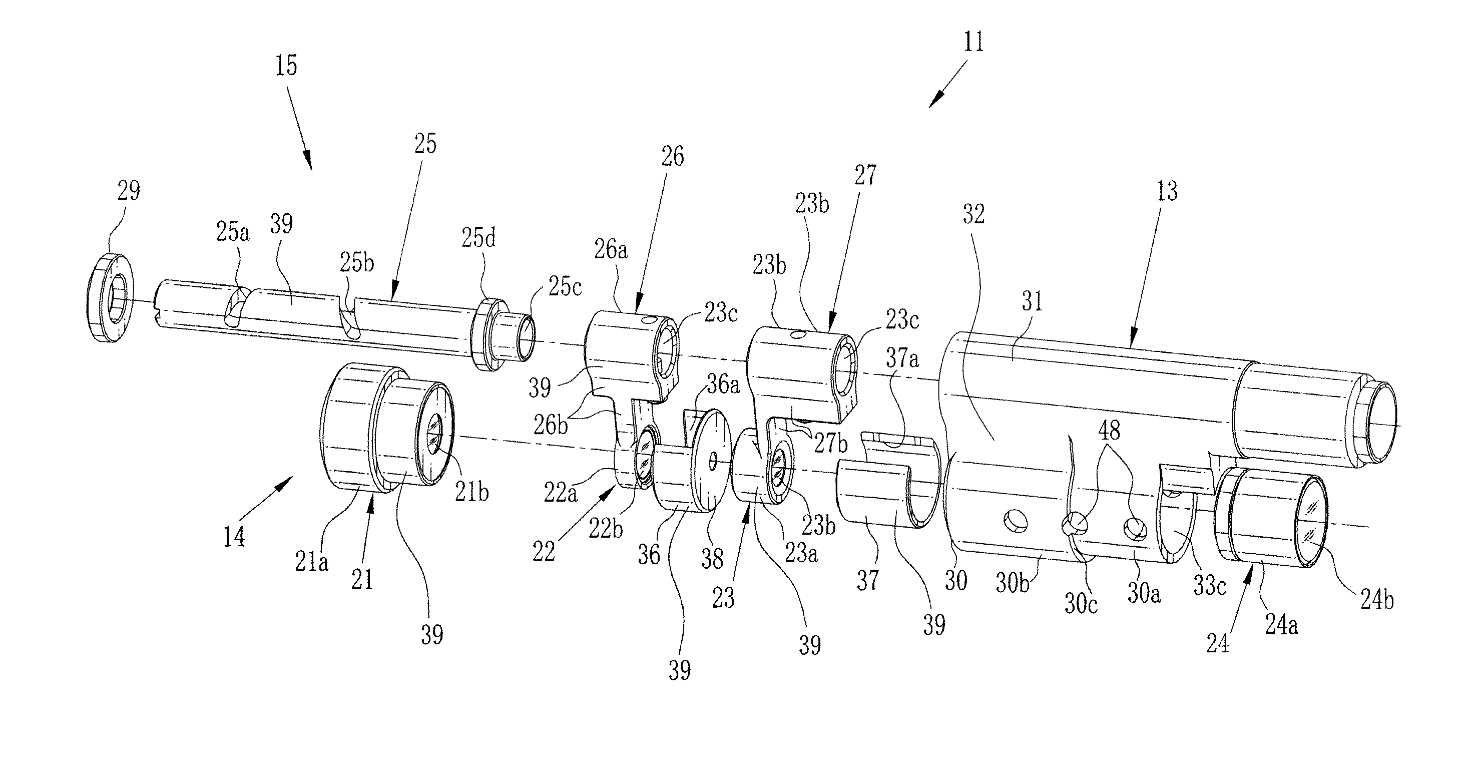
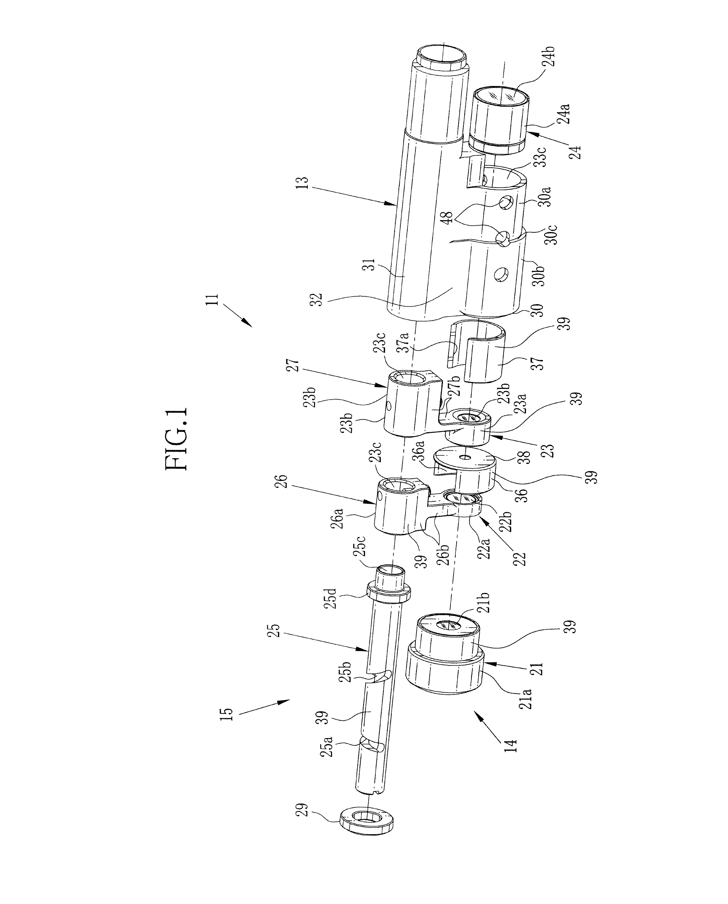
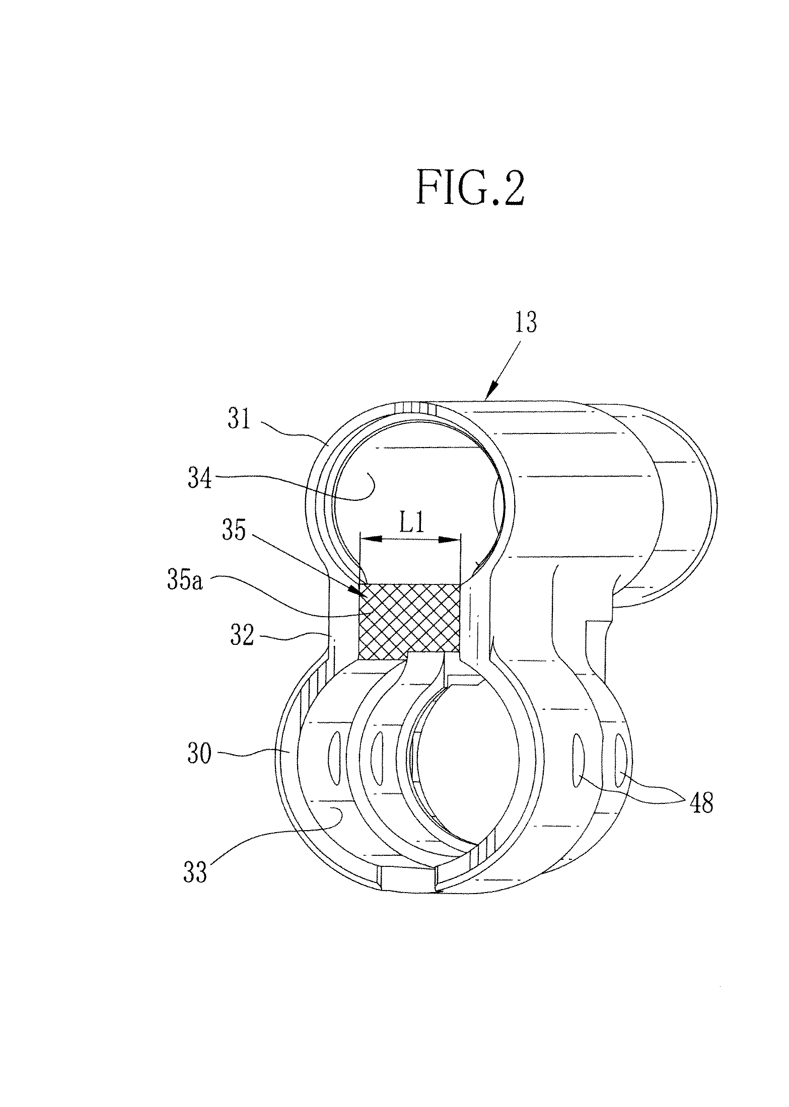
[0045]In FIGS. 1, 2 and 3, a lens unit 11 or lens assembly for imaging is illustrated. The lens unit 11 includes a housing 13, a lens system 14 and a lens moving mechanism 15.

[0046]The lens system 14 is constituted by a first stationary lens 21, a first movable lens 22, a second movable lens 23, and a second stationary lens 24. The first stationary lens 21 includes a lens holder 21a and a lens / lens group 21b (lens optics), which includes one or more lens elements and is positioned in the lens holder 21a. The first movable lens 22 includes a lens holder 22a and a lens / lens group 22b. The second movable lens 23 includes a lens holder 23a and a lens / lens group 23b. The second stationary lens 24 includes a lens holder 24a and a lens / lens group 24b.

[0047]The lens moving mechanism 15 includes a cam shaft 25, a first support device 26, and a second support device 27. The first and second support devices 26 and 27 are movable on the cam shaft 25 in an optical axis direction. The lens movin...


PUM


Abstract

A lens unit for an endoscope includes a movable lens. A rotatable cam shaft is disposed to extend in parallel with an optical axis direction. A support device is engaged with the cam shaft, for supporting the movable lens. A cam device is disposed between the cam shaft and the support device, for moving the movable lens in the optical axis direction in response to rotation of the cam shaft. A housing is provided. A first housing cavity is defined in the housing, for containing the movable lens. A second housing cavity is defined in the housing, for containing the cam shaft. An intermediate channel is formed between the first and second housing cavities, contains the support device, and includes a pair of channel surfaces, opposed to one another, formed by machining, for guiding the support device. A black surface is formed on the support device in black dyeing.

Description

BACKGROUND OF THE INVENTION[0001]1. Field of the Invention[0002]The present invention relates to a lens unit and a camera module for an endoscope. More particularly, the present invention relates to a lens unit of which parts can have precise sizes suitable for use in an endoscope, and also production can be efficiently performed by raising yield of an assembly of such parts, and a camera module for endoscope.[0003]2. Description Related to the Prior Art[0004]An electronic endoscope used widely in the medical field for diagnosis and treatment of a body of a patient. The endoscope has an elongated tube, a head assembly or tip device, and a camera module. The camera module is incorporated in the head assembly, receives object light from a body cavity, and causes a display panel to display an image of the body cavity.[0005]JP-A 2002-058635 and JP-A 2009-294540 disclose examples of the camera module having a lens system and a lens moving mechanism for changing a focal length of the lens...

Claims


Application Information

Patent Timeline
Patent Type & Authority Applications(United States)
IPC IPC(8): G02B7/04H04N5/225
CPCA61B1/05G02B7/10A61B1/0019G02B23/2484A61B1/00096G02B23/2438
Inventor KITANO, RYO
Owner FUJIFILM CORP
Learn More