Rotating shaft and motor rotor having the same

a technology of rotating shaft and motor rotor, which is applied in the direction of magnetic circuit rotating parts, dynamo-electric machines, etc., can solve the problems of rotor being stuck in the stator, delamination, and disturbance of normal operation of the motor rotor, so as to reduce the number of elements to be used, simplify the assembling operation, and simplify the structure

Inactive Publication Date: 2011-02-15
SEMICON COMPONENTS IND LLC
View PDF22 Cites 13 Cited by
  • Summary
  • Abstract
  • Description
  • Claims
  • Application Information

AI Technical Summary

Benefits of technology

[0014]Another objective of the present invention is to provide a rotating shaft and a motor rotor having the same, which have simplified structure and decreased elements.
[0023]According to the present invention, the bumps formed on an outer circumferential surface of a rotating shaft allow the magnetic bodies to be directly embedded therebetween without the need of other elements except necessary elements such as the rotating shaft and the magnetic bodies. Compared with the prior art, the present invention has simplified structure and decreases the number of elements to be used. Meanwhile, as the assembling operation only comprises embedding the magnetic bodies between adjacent engagement portions, the assembling operation is simplified and accordingly the assembly cost is decreased. Further, the design of the deformation space between the two engagement portions of each bump allows the engagement portions to undergo resilient deformation toward the deformation space during assembly of the magnetic bodies, thus preventing cracks and damages of the magnetic bodies and improving the assembly yield. Moreover, the resilient deformation can reduce or absorb size changes caused by external environment, thereby firmly fixing the magnetic bodies and preventing detaching of the magnetic bodies from the rotating shaft and prolonging the lifetime of the motor rotor.

Problems solved by technology

As the permanent magnets are fixed to the rotating shaft by adhering, the permanent magnets can easily be adversely affected by external environment factors and detached from the rotating shaft, thus inevitably disturbing normal operation of the motor rotor and even causing the rotor to be stuck in the stator.
On the other hand, if the humidity around the motor greatly changes (for example, the motor operates in a humid area or in water), the silicon steel sheets gradually gather rust and the rust further presses the adhesive layer (the cured adhesive), thereby causing delamination to occur.
Therefore, the above-describe environment factors directly shorten the lifetime of the motor.
However, as the silicon steel sheets and the permanent magnets are fabricated by different techniques having different precisions, great variation can occur during assembly engagement, which often leads to cracking of the crisp permanent magnets when the magnets are engaged with the engagement grooves, thus seriously affecting the assembly yield.
Further, because the punching precision of the grooves 111 and the machining precision of the permanent magnets 13 have a difference of at least onefold, the assembly precision is not easy to control.
If the interference fit appears, when the bolts 15 are inserted to the fixing grooves, the bolts 15 can press the permanent magnets 13 so as to cause the permanent magnets 13 to crack, thereby significantly affecting the fabrication yield and greatly increasing the fabrication cost.
Also, the large number of the embedding teeth 25 leads to high element cost, high assembly cost and high warehousing cost.

Method used


Image

  • Rotating shaft and motor rotor having the same
  • Rotating shaft and motor rotor having the same
  • Rotating shaft and motor rotor having the same

Examples


Embodiment Construction

[0029]The following illustrative embodiments are provided to illustrate the disclosure of the present invention, these and other advantages and effects can be apparent to those skilled in the art after reading the disclosure of this specification.

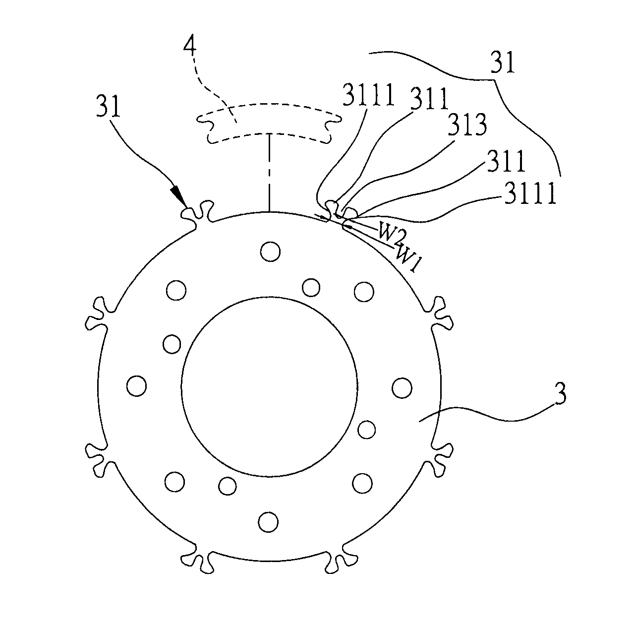
[0030]FIG. 3A is a structural diagram of a rotating shaft according to a preferred embodiment of the present invention and FIG. 3B is a locally enlarged view of FIG. 3A. As shown in FIGS. 3A and 3B, the rotating shaft 3 of the present invention has a plurality of bumps 31 spacedly formed along an outer circumferential surface thereof such that magnetic bodies 4 can be embedded between adjacent bumps 31, wherein, the bumps 31 are each formed with two engagement portions 311 extending outwardly and bilaterally and a deformation space 313 between the engagement portions 311, the engagement portions 311 can undergo resilient deformation toward the deformation space 313 when subjected to a force.

[0031]In the present embodiment, the rotating shaf...


PUM


Abstract

A rotating shaft disclosed by the present invention includes a plurality of bumps spacedly formed along an outer circumferential surface thereof. The bumps are each formed with two engagement portions extending outwardly and bilaterally and a deformation space therebetween. The engagement portions undergo resilient deformation toward the deformation space when subjected to a force, thus providing stable engagement with a magnetic body, protecting the magnetic body from cracks and damages during assembling, and enhancing yield. The present invention further discloses a motor rotor having the above-described rotating shaft.

Description

BACKGROUND OF THE INVENTION[0001]1. Field of the Invention[0002]The present invention relates generally to a motor rotor, and more particularly to a motor rotor and rotating shaft thereof having engagement structure for fixing magnetic bodies to the rotating shaft.[0003]2. Description of Related Art[0004]A motor (electromotor) is used to convert electrical energy into mechanical energy so as to provide rotary motion. Besides directly providing rotary motion, the motor also can convert rotary mechanical energy into linear motion or vibrating motion by combining with different mechanisms.[0005]A motor for providing rotary motion comprises a stator and a rotor, wherein the stator is the stationary part of the motor, which provides a magnetic field; the rotor is the rotary part of the motor, which rotates according to the magnetic field. The rotor generally comprises a rotating shaft formed by stacking a plurality of silicon steel sheets and a plurality of permanent magnets spacedly adh...

Claims


Application Information

Patent Timeline
Patent Type & Authority Patents(United States)
IPC IPC(8): H02K1/28
CPCH02K1/2773H02K1/278
Inventor YANG, SHIH-JENTU, HUNG-SENCHEN, I-HSINGYANG, CHEN-CHA
Owner SEMICON COMPONENTS IND LLC
Why Eureka
Try Eureka