Backlight module and display module

A technology of backlight module and display module, which is applied in the directions of optics, electric light source, light source fixing, etc., can solve the problems of increasing production cost and assembly complexity, etc.

Inactive Publication Date: 2012-06-20
AU OPTRONICS CORP
View PDF7 Cites 12 Cited by
  • Summary
  • Abstract
  • Description
  • Claims
  • Application Information

AI Technical Summary

Problems solved by technology

In this way, the production cost and assembly complexity are also increased.

Method used


Image

  • Backlight module and display module
  • Backlight module and display module
  • Backlight module and display module

Examples


Embodiment Construction

[0097] image 3 A display module according to an embodiment of the present invention is shown. Figure 4 is a cross-sectional view of the display module of this embodiment. In order to clearly express the structural characteristics, image 3 Components such as the front frame, the display panel, and the bearing frame are omitted, and the local structure is shown in a partially enlarged view.

[0098] Such as image 3 and Figure 4 As shown, the display module 200 of this embodiment mainly includes a display panel 400 and a backlight module 300 , wherein the backlight module 300 is mainly composed of a bottom plate 310 , a light guide plate 320 , a supporting frame 330 , a buffer material 340 and a baffle 350 . The light guide plate 320 is disposed on the bottom plate 310, and the light guide plate 320 includes a top surface 320a, a bottom surface 320b opposite to the top surface 320a, and a plurality of side surfaces 320c connected between the top surface 320a and the bott...


PUM


Abstract

The invention discloses a display module and a backlight module. The display module includes the backlight module and a display panel arranged on the backlight module. The backlight module includes a base plate, a light guide plate, a support frame, a buffer material and a baffle. The light guide plate is arranged on the base plate and includes the top face, the bottom face and a plurality of side faces connecting between the top face and the bottom face. The support frame surrounds the light guide plate. The buffer material is arranged on at least one side of the light guide plate and includes the top wall, the bottom wall and the side wall. The top wall is arranged on the outer periphery of the top face of the light guide plate. The bottom wall leans between the base plate and the bottom face of the light guide plate. The side wall connects with the top wall and the bottom wall and wraps at least one side face of the light guide plate. The baffle is arranged on the base plate vertically and is disposed on at least one side of the light guide plate. The side wall of the buffer material leans between the baffle and at least one side face of the guide plate.

Description

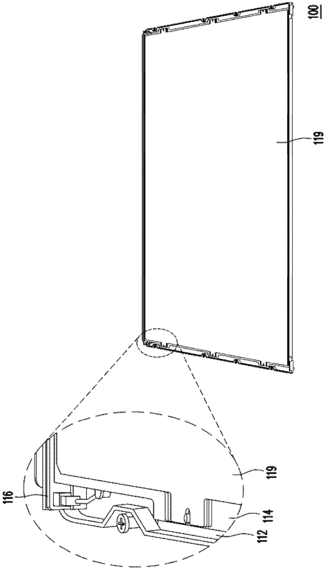
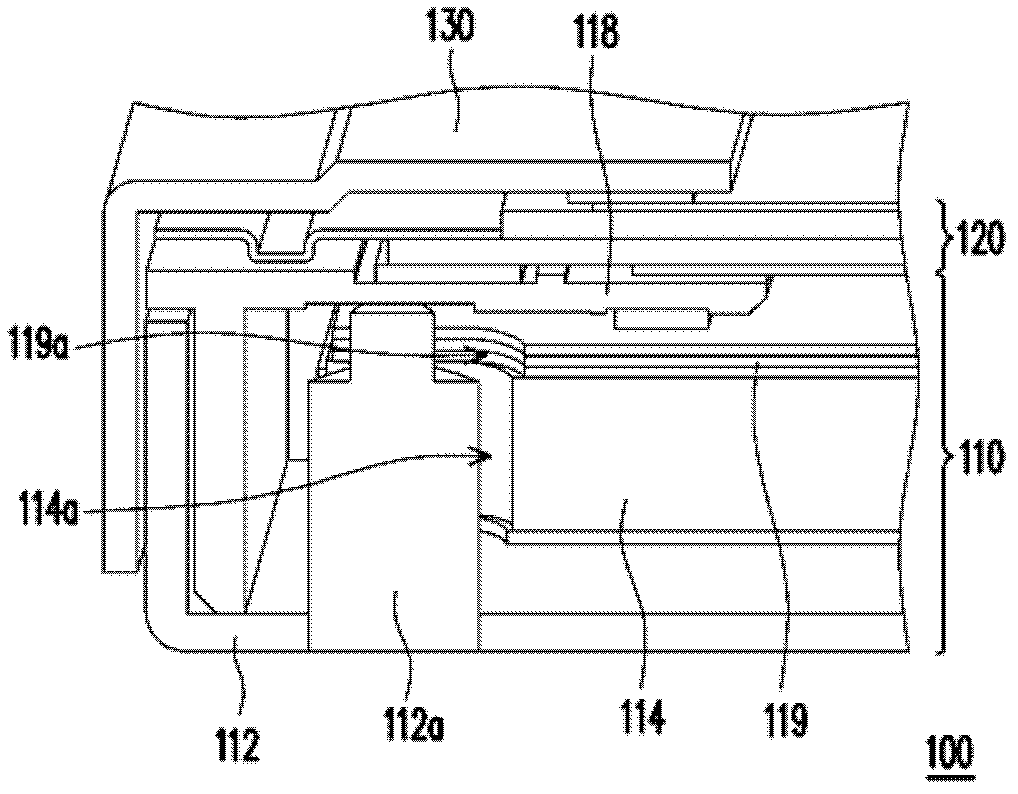
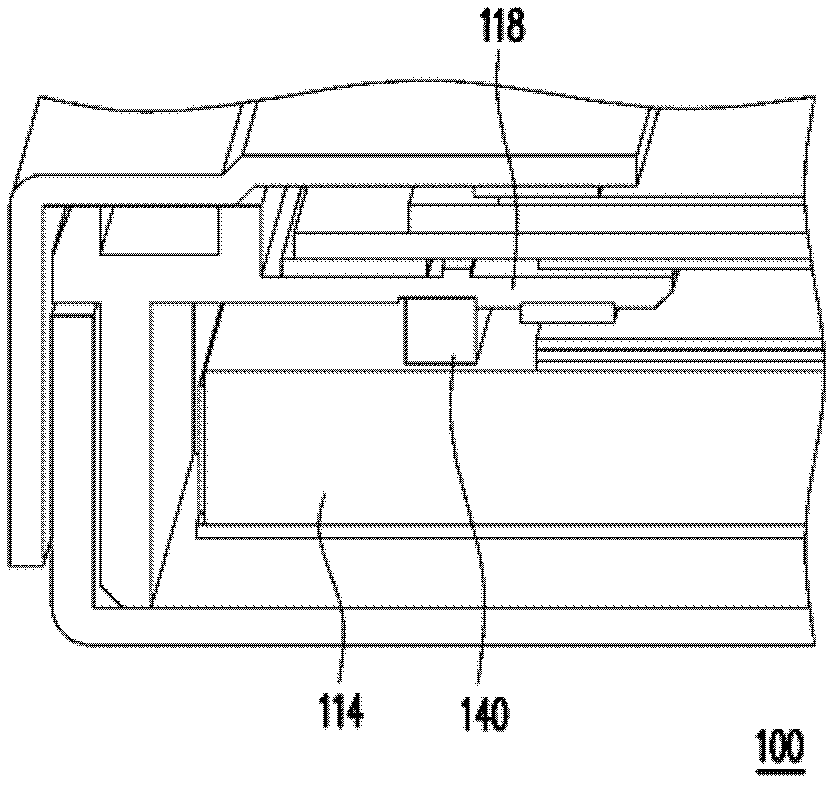
technical field [0001] The present invention relates to a backlight module and a display module, and in particular to a backlight module and a display module which can take into account both the stress buffering of the light guide plate and the positioning effect of the optical film. Background technique [0002] With the increasing maturity of optoelectronic technology and semiconductor manufacturing technology, flat panel display devices are developing vigorously. Among them, the liquid crystal display has gradually replaced the traditional cathode ray tube display due to its advantages of low voltage operation, no radiation scattering, light weight and small size, and has become the mainstream of display products in recent years. [0003] figure 1 A conventional liquid crystal display module is shown. Figure 2A for figure 1 A cross-sectional view of an LCD module. Figure 2B for figure 1 Another cross-sectional view of the LCD module. In order to clearly express th...

Claims


Application Information

Patent Timeline
Patent Type & Authority Applications(China)
IPC IPC(8): F21S8/00F21V7/00F21V17/10G02F1/13357
Inventor 曾泓晟魏肇治薛文林
Owner AU OPTRONICS CORP
Why Eureka
Try Eureka