Voice coil motor

A voice coil motor and coil technology, applied in installation, optics, instruments, etc., can solve the problems of multiple rework, material waste, time-consuming and labor-intensive problems

Inactive Publication Date: 2012-07-11
HONG FU JIN PRECISION IND (SHENZHEN) CO LTD +1
View PDF6 Cites 13 Cited by
  • Summary
  • Abstract
  • Description
  • Claims
  • Application Information

AI Technical Summary

Problems solved by technology

The above factors lead to material waste, repeated rework, time-consuming and labor-intensive

Method used


Image

  • Voice coil motor
  • Voice coil motor
  • Voice coil motor

Examples


Embodiment Construction

[0045] The voice coil motor provided by the technical solution will be described in detail below with reference to the accompanying drawings and specific embodiments.

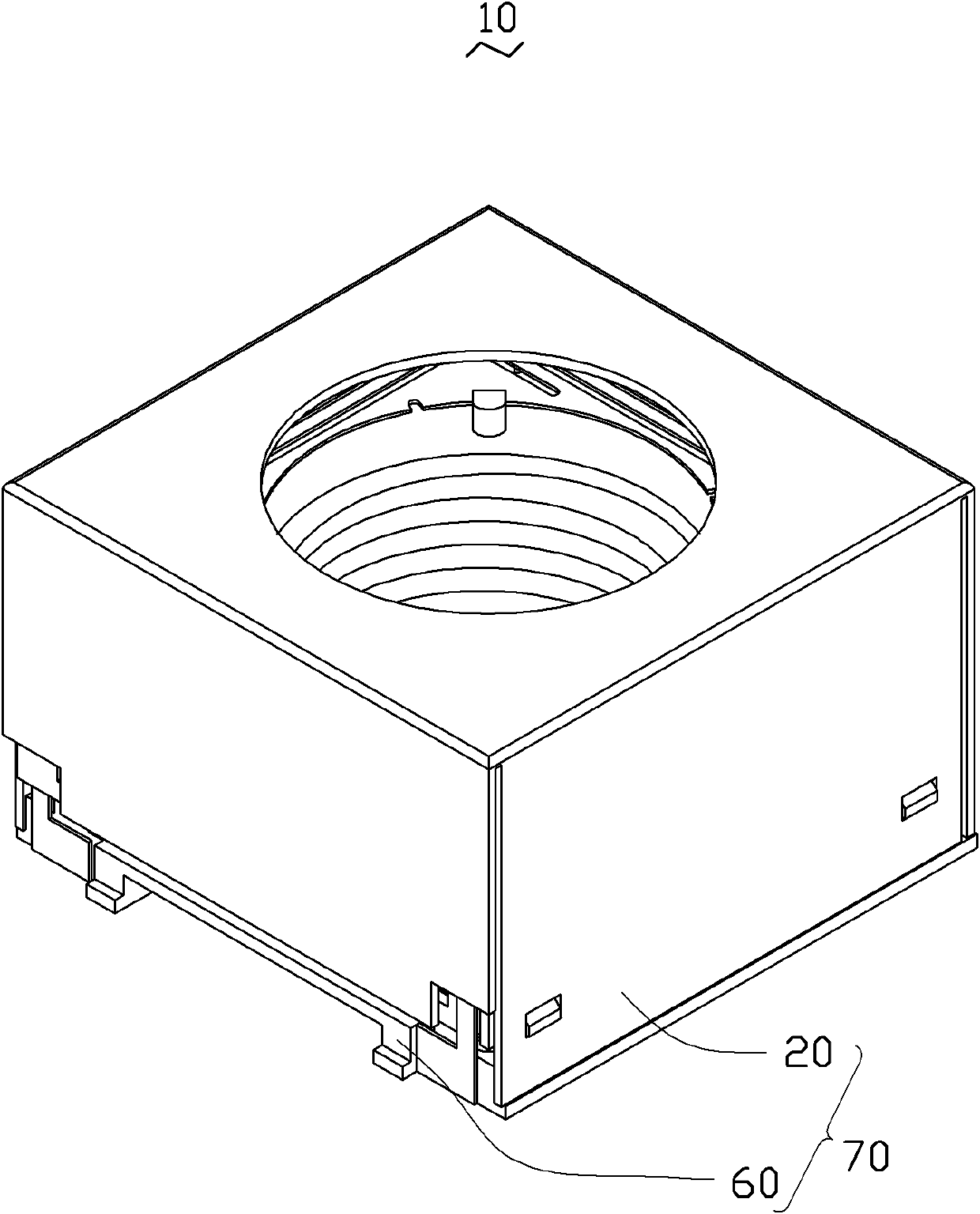
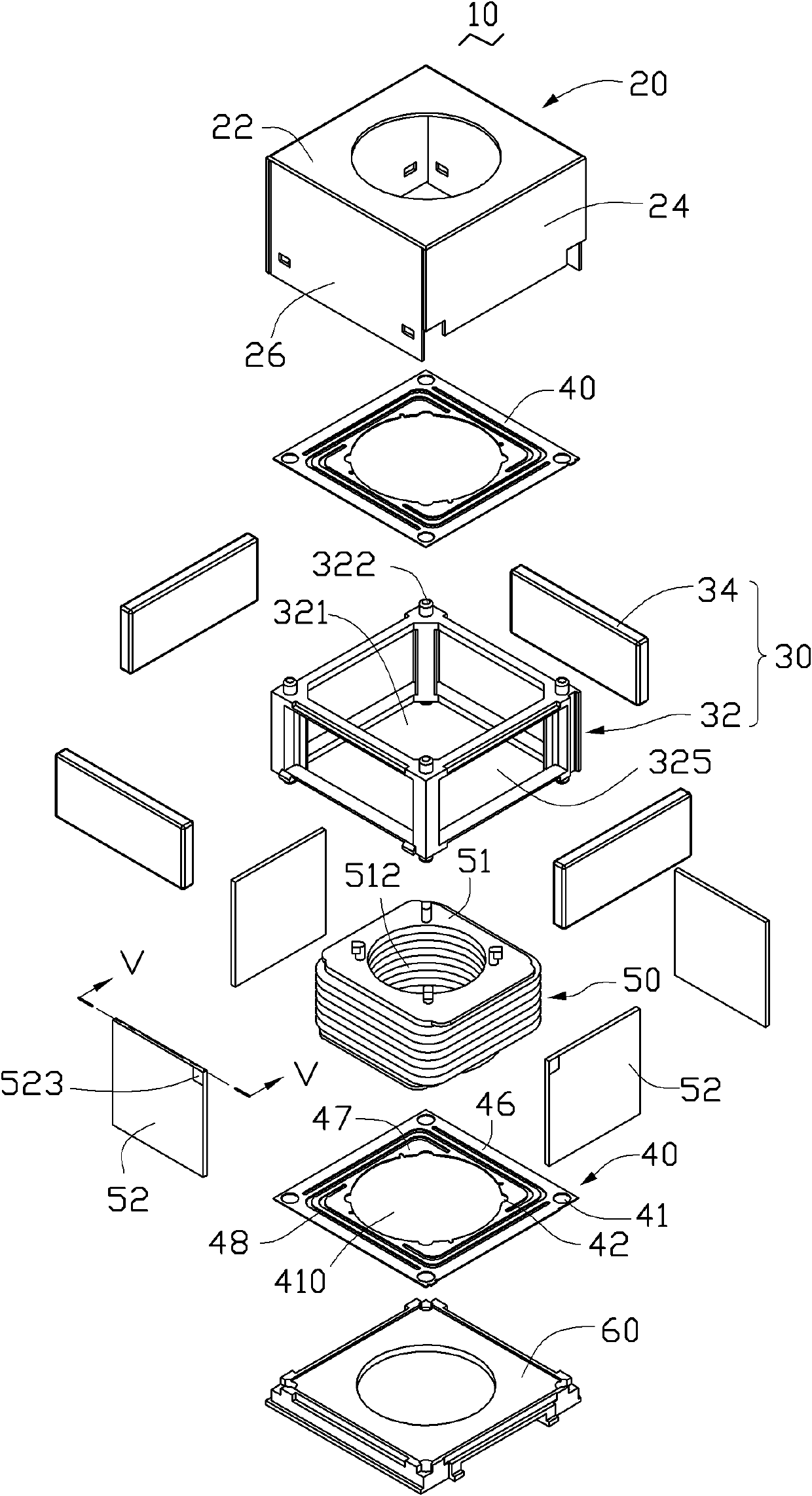
[0046] see figure 1 and figure 2 , the voice coil motor 10 provided by the embodiment of the present invention includes an isolation box 70 , a fixed assembly 30 , two elastic pieces 40 and a movable assembly 50 .

[0047] The isolation box 70 is used to eliminate external electromagnetic interference to the voice coil motor 10 and prevent the electromagnetic interference of the voice coil motor 10 from affecting the operation of its external electronic components. The isolation box 70 includes a housing 20 and a base 60 . The housing 20 can be made of magnetic shielding materials such as nickel-iron alloy, conductive plastic, surface conductive material, and conductive glass. The housing 20 has a quadrangular bottom plate 22 , two first side plates 24 respectively disposed on opposite sides of the bottom p...


PUM


Abstract

The invention relates to a voice coil motor, which comprises a lens cylinder, a magnet, at least one spring plate and a printed circuit board process coil, wherein the lens cylinder is provided with a lateral wall and a first accommodating cavity for accommodating a lens; the magnet surrounds the lateral wall and is separated from the lateral wall; the at least one spring plate is connected with the lens cylinder; and the printed circuit board process coil is fixed on the lateral wall and is opposite to the magnet. The printed circuit board process coil generates a magnetic field force with the magnet after being electrified, to drive the lens cylinder to move along the axis. The at least one spring plate generates deformation when the lens cylinder moves, and applies a restoring force to the lens cylinder, so that the lens cylinder moves to a preset position from an initial position under the actions of the magnetic field force and the restoring force, is then still and restores to the initial position after the current of the printed circuit board process coil is powered off. The voice coil motor is convenient to assemble.

Description

technical field [0001] The invention relates to a voice coil motor, in particular to a voice coil motor including a printed circuit board process coil. Background technique [0002] Voice coil motors have the advantages of small size, low power consumption, and low price, and are suitable as drivers for electronic products with camera functions such as digital cameras, mobile phones, and digital video cameras. [0003] Existing voice coil motors usually include a copper wire coil, a movable barrel and a magnet. The coil is wound on the outer wall of the movable tube, the magnet is opposite to the coil, and the movable tube is used for accommodating the lens. When the coil current is applied, an interaction force will be generated between the coil and the magnet, and the force will drive the movable barrel to move along the optical axis of the lens, thereby changing the distance between the lens and the image sensor of the electronic product , to achieve the effect of zoomi...

Claims


Application Information

Patent Timeline
Patent Type & Authority Applications(China)
IPC IPC(8): H02K33/02G02B7/04
Inventor 辜炳翰
Owner HONG FU JIN PRECISION IND (SHENZHEN) CO LTD
Why Eureka
Try Eureka