Eureka AIR delivers breakthrough ideas for toughest innovation challenges, trusted by R&D personnel around the world.

A method for manufacturing a separator plate for a fuel cell, a separator plate, and an intermediate product for a separator plate

A technology of fuel cells and manufacturing methods, applied in the direction of fuel cells, layered products, final product manufacturing, etc., can solve the problems of fragile manufacturing, expensive bipolar plates, etc., and achieve long durability and long use The effect of high life and energy density

Active Publication Date: 2019-10-08
CELLCENTRIC GMBH & CO KG +1
View PDF3 Cites 2 Cited by
  • Summary
  • Abstract
  • Description
  • Claims
  • Application Information

AI Technical Summary

Problems solved by technology

[0009] However, bipolar plates made of plastic material with carbon black as filler are fragile and expensive to manufacture
Also, metal bipolar plates are expensive

Method used


Image

  • A method for manufacturing a separator plate for a fuel cell, a separator plate, and an intermediate product for a separator plate
  • A method for manufacturing a separator plate for a fuel cell, a separator plate, and an intermediate product for a separator plate

Examples


Embodiment Construction

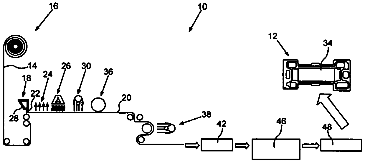
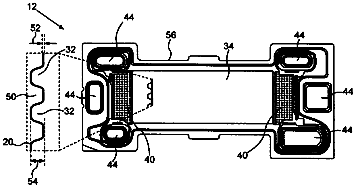
[0060] exist figure 1 The manufacturing equipment 10 schematically shown in is used to manufacture insulation panels, wherein, in figure 2 The separating plates of the bipolars in plan view are shown in the form of bipolar plates, which can be produced in the production plant 10 . The bipolar plates 12 are used for the fuel cells of a fuel cell stack, which may be used, for example, in motor vehicles.

[0061] When producing the bipolar plate 12 , first a carrier material is provided here in the form of a carrier film 14 . This can be a carrier film 14 wound on a roll 16 . In particular biaxially stretched or biaxially oriented polyester films can be used as carrier film 14 .

[0062] The carrier film 14 is unwound from the roll 16 and then fed to the further processing stations of the production plant 10 . A mixture 28 is applied to the carrier film 14 at the first processing station 18 , the mixture comprising the electrically conductive material 20 , wherein the materi...


PUM

PropertyMeasurementUnit
thicknessaaaaaaaaaa
double bond equivalentaaaaaaaaaa

Abstract

The invention relates to a method for manufacturing a separator plate (12) for a fuel cell, wherein a curable and electrically conductive material (20) is applied to a substrate material (14). A flowfield (34) for a reactant which can be supplied to the fuel cell is formed in the material (20). After the flow field (34) is formed, the material (20) is cured. The invention also relates to a separator plate (12) for a fuel cell and an intermediate product for a separator plate (12).

Description

technical field [0001] The present invention relates to a method of manufacturing a separator for a fuel cell. Furthermore, the invention relates to separator plates for fuel cells, which may be applied, for example, in fuel cell stacks and intermediate products for such separator plates. Background technique [0002] The basic structure of a polymer electrolyte membrane fuel cell - PEMFC for short - is as follows. A PEMFC comprises a membrane electrode assembly—MEA for short—consisting of an anode, a cathode and a polymer electrolyte membrane (also called ionomer membrane)—PEM for short—arranged between them. The MEA itself is instead arranged between two partition plates, wherein one partition plate has channels for distributing the fuel and the other partition plate has channels for distributing the oxidant, and wherein the channels face the MEA. The channels form a channel structure, the so-called Flow Field or flow field. The electrodes, anode and cathode can in part...

Claims


Application Information

Patent Timeline
Patent Type & Authority Applications(China)
IPC IPC(8): H01M8/1018H01M8/0221H01M8/0226H01M8/0254
CPCH01M8/1018H01M8/0221H01M8/0226H01M8/0254H01M2008/1095Y02E60/50H01M8/0258Y02P70/50B32B2457/18
Inventor 法尔克·乌尔曼海尔格·沃塔
Owner CELLCENTRIC GMBH & CO KG
Why Eureka
Eureka Blog
Learn More