Image Detecting Module and Lens Module

a technology of image detection and lens module, applied in the field of lenses module, can solve the problem of increasing costs and achieve the effect of effectively reducing thickness

Inactive Publication Date: 2011-05-05
ABILITY ENTERPRISE CO LTD
View PDF23 Cites 12 Cited by
  • Summary
  • Abstract
  • Description
  • Claims
  • Application Information

AI Technical Summary

Benefits of technology

[0008]In view of the above, one object of the present invention is to provide a lens module in which the filter is placed on a stand-alone socket to avoid the deployment of filter placement area inside the lens barrel, wherein the thickness is effectively reduced and the lens module becomes thinner.
[0009]Another object of the present invention is to provide a lens module in which a holder is utilized to fix the filter on the stand-alone socket. The holder allows the lens module to be reassembled, facilitates the assembling process, and raises the yield of assembly.
[0010]Still another object of the present invention is to provide a lens module in which a holder is used to fix the filter on the stand-alone socket. When the lens module is de-assembled, damages to the filter and the socket can be prevented by using such method and the production cost can thus be effectively reduced.

Problems solved by technology

In the re-assembling process, the filter 94 dispensed and fixed on the socket 91 will be damaged and the cost is thus increased.

Method used


Image

  • Image Detecting Module and Lens Module
  • Image Detecting Module and Lens Module
  • Image Detecting Module and Lens Module

Examples


first embodiment

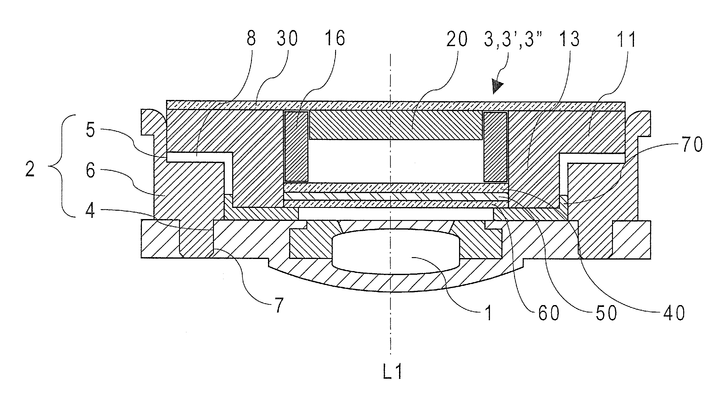
[0031]The image sensing module 3 of the first embodiment comprises a socket 10, an image sensor 20 disposed in the rectangular opening 12 of the socket 10, a circuit board 30 electrically connected to the image sensor 20, a shading sheet 40, an elastic element 50, a filter 60, and a holder 70.

[0032]The socket 10 comprises a base plate 11 on which a hollowed-out rectangular opening 12 surrounded by a barrel portion 13 is disposed, wherein the barrel portion 13 comprises an inner sidewall 14 surrounding the same axis L1 as the lens barrel 2 of the lens module and an outer sidewall 15 on the other side of the inner sidewall 14. The above-mentioned inner sidewall 14 and the rectangular opening 12 form an accommodating space; therefore, when the circuit board 30 is dispensed to be fixed below the socket 10, the image sensor 20 on the circuit board 30 can be placed in the accommodating space formed by the inner sidewall 14 and the rectangular opening 12. Moreover, a plurality of rectangul...

third embodiment

[0042]Furthermore, the design of the image sensing module of the lens module in FIG. 3 can be the same as the one in FIG. 12. The socket and the holder of the image sensing module in the third embodiment can be designed as such shown in FIG. 13 and FIG. 14.

[0043]The image sensing module 3″ of the third embodiment is similar to the image sensing module 3′ of the second embodiment and includes a socket 10″, an image sensor 20 placed in the rectangular opening 12″ of the socket 10′, a circuit board 30 electrically connected to the image sensor 20, a shading sheet 40, an elastic element 50, a filter 60, and a holder 70″.

[0044]The socket 10″ of the image sensing module 3″ of the third embodiment differs from the socket 10′ of the second embodiment in that it includes a base plate 11″ on which a rectangular opening 12″ is formed by the surrounding of the octagonal barrel portion 13″ with four corners being cut out, wherein the barrel portion 13″ is formed by an inner sidewall 14″ surround...


PUM


Abstract

An image detecting module includes a socket, a circuit board, an image sensor, an elastic element, a filter and a holder. The socket comprises an inner circumference wall along a main axis for defining an inner space and a platform that extended from the inner circumference wall. Pluralities of mounting holes are provided on the holder and pluralities of protrusions are provided on the socket; thus the elastic element and the filter could be fixed between the platform and the holder by fitting the protrusions into the mounting holes.

Description

BACKGROUND OF THE INVENTION[0001]1. Field of the Invention[0002]The present invention relates to a lens module, and more particularly, to a lens module of digital camera formed with components such as the filter being fixed on a stand-alone socket using the holder.[0003]2. Description of the Prior Art[0004]Currently on the market, mobile phones (or cell phones) with photo-taking function, digital cameras, and video cameras are all deployed with a lens module. A lens module consists essentially of a lens group, a lens barrel, and an image sensor. FIG. 1 is a views of lens module of the conventional prior art. The lens module consists of the lens group 81, lens barrel 82, and image sensor 83. The lens group 81 are placed inside the lens barrel 82 and include a lens 811 used for focalization and a filter 812 for eliminating specific optical frequency. The image sensor 83 is equipped on one side of the lens barrel 82 and includes one transparent cover plate 831, an image sensing chip 83...

Claims


Application Information

Patent Timeline
Patent Type & Authority Applications(United States)
IPC IPC(8): H04N5/335
CPCH04N5/2257H04N5/2253H04N23/57H04N23/54
Inventor LU, CHIEN-HSINWU, ZHENG-YU
Owner ABILITY ENTERPRISE CO LTD
Why Eureka
Try Eureka