Device for the production of a three-dimensional object

a three-dimensional object and device technology, applied in the direction of additive manufacturing, additive manufacturing processes, additive manufacturing with solids and fluids, etc., can solve the problem of general overheating in the construction space, achieve energy-efficient temperature control, improve energy efficiency of the entire system, and facilitate energy utilization.

Active Publication Date: 2018-02-13
ARBURG GMBH & CO KG
View PDF5 Cites 4 Cited by
  • Summary
  • Abstract
  • Description
  • Claims
  • Application Information

AI Technical Summary

Benefits of technology

[0010]In order to obtain as favorable an energy utilization as possible and an energy-efficient temperature control, the temperature-controllable construction space is surrounded by a construction space surround, in which at least the outlet of the discharge unit and also the processing unit for the material to be processed are accommodated. Since the processing unit introduces heat by supplying the heated liquid material, an excess of heat generally occurs in the construction space. This is additionally reinforced by the heating during the melting of the material at the processing unit as a result of heat radiation. As a result, the construction space with the object arranged therein and also the drops from the instant they leave the discharge unit are in a temperature range that can be influenced by temperature control. However, the temperature control of the construction space is important or necessary to optimally influence the bonding of the applied drops to the already produced structural part, i.e. the object to be created. Namely, the temperature difference between the melting form of the drop and the surface on the object can be influenced individually thereby. This ability to be influenced is heavily dependent on the material, e.g. in the case of crystalline or amorphous plastics. On the other hand, it is expedient for an energy-optimized consideration to separate the heat flow from the processing unit in the direction of the pressure generating unit in order to also retain the heat generated there where it can be used beneficially. The energy efficiency of the entire system can be increased as a result. This separation is achieved by an insulating element, which is interposed between the processing unit and the pressure generating unit. The construction space surround can be insulated altogether to prevent heat flow to the outside as far as possible.
[0012]This precision of parts can be improved even further by configuring the machine table, which supports above all the processing unit and object support as mutually spaced parts of the device, to be sufficiently rigid that, on the one hand, temperature-related expansions are only noticeable to a small extent, while on the other hand the temperature-controlled construction space also has as little contact with this arrangement as possible with respect to temperature.

Problems solved by technology

Since the processing unit introduces heat by supplying the heated liquid material, an excess of heat generally occurs in the construction space.

Method used


Image

  • Device for the production of a three-dimensional object
  • Device for the production of a three-dimensional object
  • Device for the production of a three-dimensional object

Examples


Embodiment Construction

[0017]The invention will now be explained in more detail in an exemplary manner with reference to the attached drawings. However, the exemplary embodiments are only examples that are not intended to restrict the inventive concept to a specific arrangement. Before describing the invention in detail, it is pointed out that it is not restricted to the respective structural parts of the device or the respective process steps, since these structural parts and processes can vary. The terms used here are merely intended to describe particular embodiments and are not used for restriction. Moreover, when the singular or indefinite articles are used in the description or in the claims, this also relates to the plural of these elements unless the overall context clearly indicates otherwise.

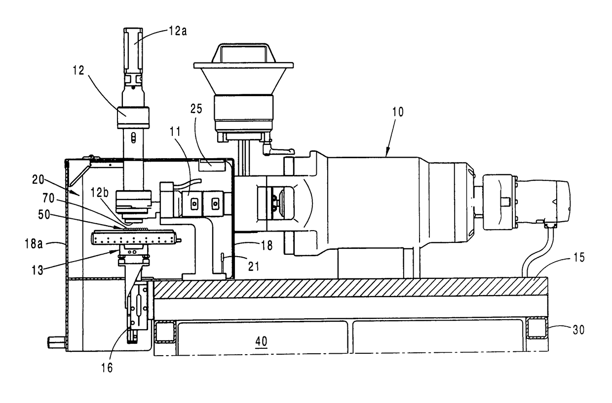
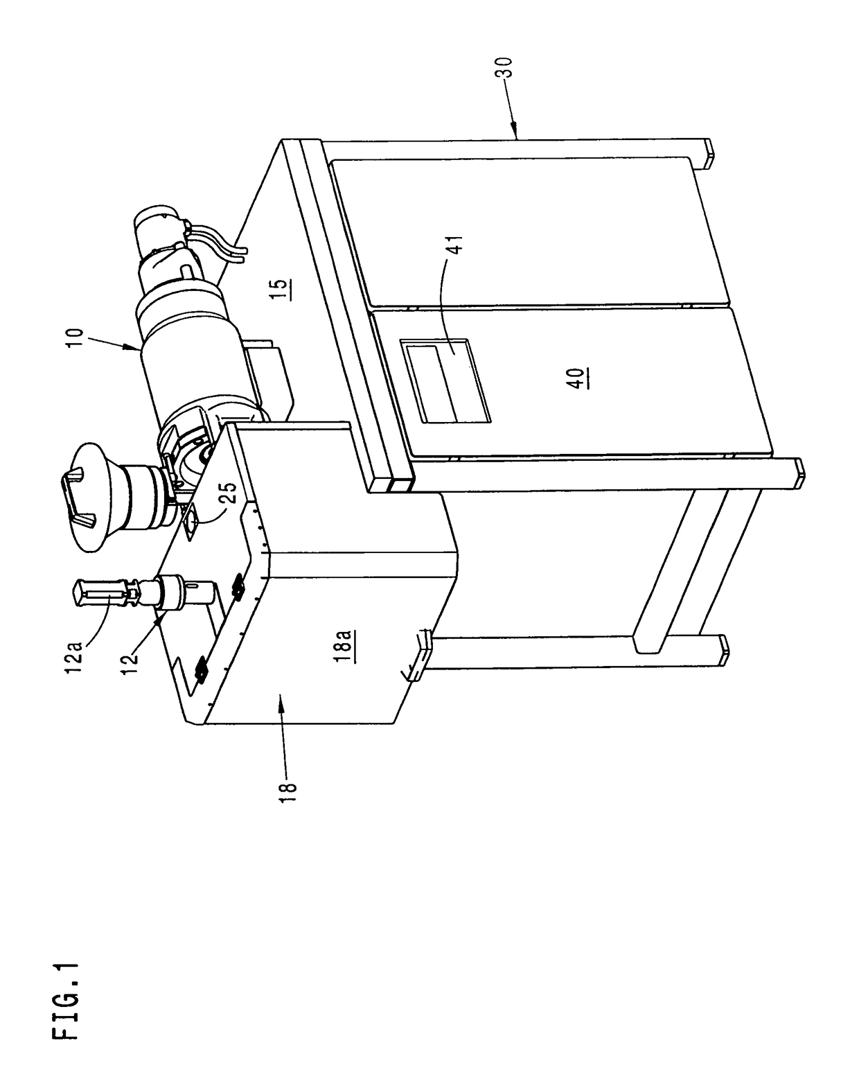
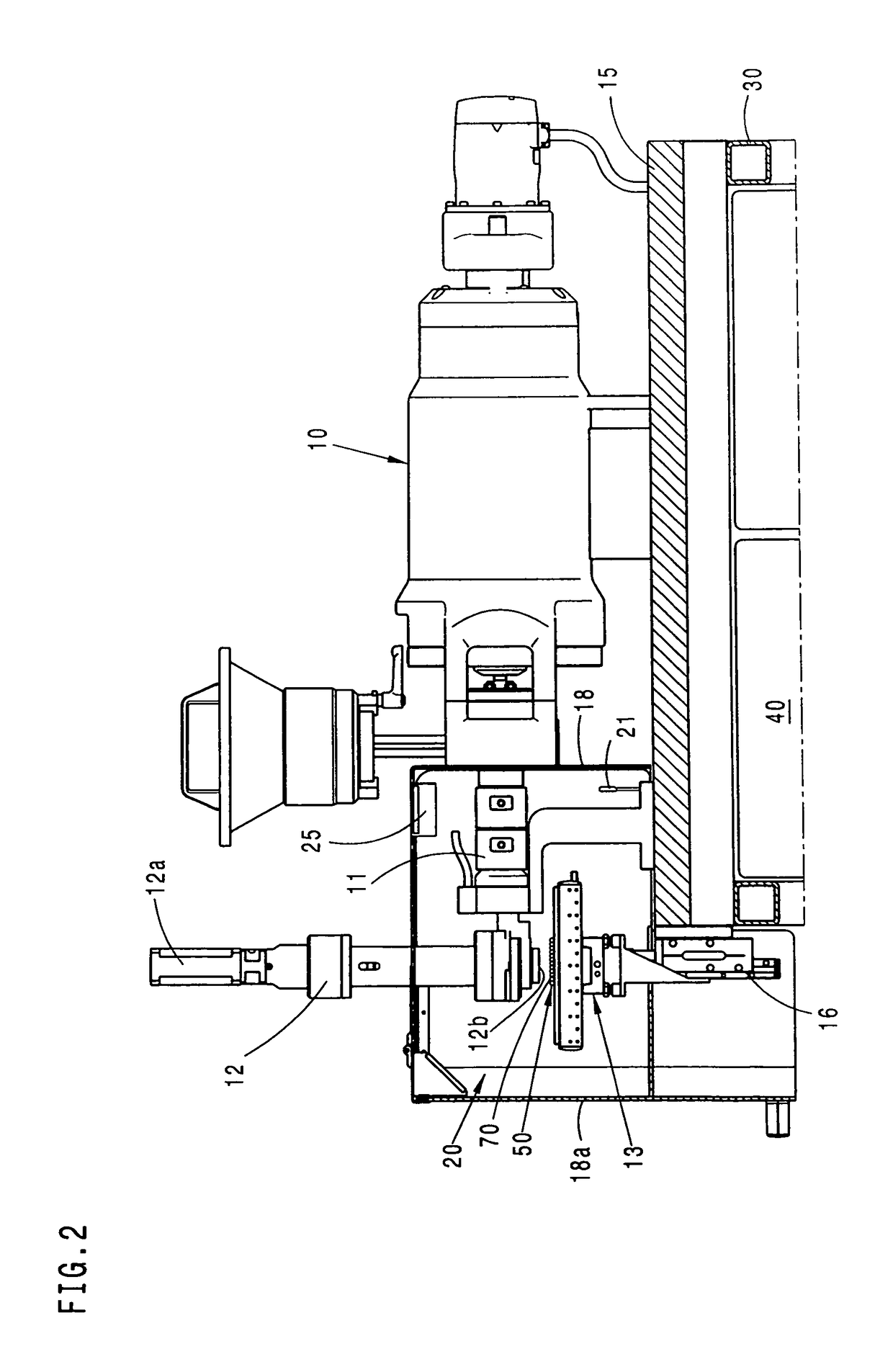
[0018]The Figures show a device for the production of a three-dimensional object 50 or a structural part from hardenable material that is either present in the starting state in a fluid phase or can be lique...


PUM

PropertyMeasurementUnit
dynamic coefficient of viscosityaaaaaaaaaa
pressuresaaaaaaaaaa

Abstract

A device for producing a three-dimensional object from hardenable material has a construction space (20) for constructing the object (50), a temperature control unit for controlling the temperature of the construction space (20), and a preparation unit (11) for preparing the hardenable material in such a way that the material is in the fluid phase. A pressure generation unit (10) applies pressure to the fluid phase in the preparation unit. A discharge unit (12) is provided for discharging the hardenable material through an outlet (12b) in the form of drops in the direction of the construction space (20). In order to optimize the energy required to control the temperature that promotes bonding of the material on the object (50), the temperature-controlled construction space (20) is surrounded by a construction space frame (18) in which at least the outlet of the discharge unit (12), the preparation unit (11), and the object support (13) for producing the object are accommodated.

Description

CROSS REFERENCE TO RELATED APPLICATIONS[0001]The present application claims the priority of German patent application 10 2008 106 615.6 filed on 16 Jun. 2011, the entire contents of which are herein incorporated by reference.FIELD OF THE INVENTION[0002]The invention relates to a device for the production of a three-dimensional object from hardenable material.BACKGROUND[0003]In plastic part production, parts are produced by injection molding or extrusion in large batch sizes and series using molds. The advantage of plastic injection molding rests in particular on the highly precise production of complex part geometries, wherein the versatility of operation of the injection molding process covers the requirements for an inexpensive and economical production of plastic parts in an optimal manner.[0004]At the same time, demand for plastic parts in a unit number of one and small batch sizes such as pattern parts, for example, is increasing with the requirement of provision in a very shor...

Claims


Application Information

Patent Timeline
Patent Type & Authority Patents(United States)
IPC IPC(8): B29C67/00B29C64/112B29C64/165B29C64/20
CPCB29C64/165B29C64/112B29C64/20B29C64/295
Inventor KRAIBUHLER, HERBERTDUFFNER, EBERHARD
Owner ARBURG GMBH & CO KG
Why Eureka
Try Eureka