Mold-closing unit for an injection molding machine, and method for locking a force transmission element

a technology of injection molding machine and locking element, which is applied in the field of molding closing unit for injection molding machine and the method of locking force transmission element, to achieve the effect of high degree of precision, smooth locking movement, and high degree of precision

Pending Publication Date: 2021-11-04
ARBURG GMBH & CO KG
View PDF0 Cites 0 Cited by
  • Summary
  • Abstract
  • Description
  • Claims
  • Application Information

AI Technical Summary

Benefits of technology

[0027]The disclosure provides a method for locking a force transmission element to one of the mold carriers of the injection molding machine. For this method, the injection molding machine has the structural elements comprising a stationary mold carrier, a movable mold carrier, a mold drive device, and at least one force transmission element, wherein, during mold closure of the parts of the injection mold, an actuable portion of a force transmission element is locked with positive engagement to the other mold carrier by means of a plurality of locking elements of at least one locking device that are arranged radial in relation to the force transmission element. In the condition locked in this way, a closing force that acts by way of the force transmission element is applied. Because the locking elements on at least one actuator that is movable in the closing direction are configured to be brought into and out of positively locking operative connection with the actuable portion transversely to the closing direction and in a forced guidance arrangement during mold closure, and because the actuator within the locking device is at the same time connected to a piston of a piston-and-cylinder unit that applies the closing force, this does not only produce a compact structural solution. When the actuator is moved in the closing direction, the locking elements are guided in a cam guide that takes the form of a forced guidance arrangement, and these take the form of clamping jaws that are configured to be brought into operative connection with the actuable portion. The forced guidance arrangement makes it possible to bring the locking elements into the locking position in a manner that is sustainably reproducible and reliable, so that even after multiple cycles a high degree of precision can still be ensured. In addition, the cam guide contributes to smooth performance of the locking movement, which operates reliably even under high forces. Moreover, the cam guide makes possible a high degree of precision and thus also reproducible predefinability of the locking. At the same time, this has the effect that no positioning errors arise, and this consequently contributes to the operational safety and also to increasing the precision of the parts to be made.
[0028]Favorably, the linear movement of the actuator and the cam guide axially in the closing direction results in the movement of the locking elements, which is transverse to the closing direction and radial in relation to the longitudinal extent of the force transmission element. This contributes to the possibility of performing the locking reliably without any need for the deformation of the actuator which was required hitherto.
[0029]Preferably, the locking elements are forcibly guided on the actuator, mounted on rollers in the cam guide. In addition, or as an alternative, in an advantageous embodiment the locking elements may also be guided on both sides on rollers in a movement channel of the forced guidance arrangement. Each of these individually contributes to increasing the precision, since by this means the course of movement of the locking elements is predefinable predetermined. This results in exact locking and hence also, even under high forces, reliable force transmission and enhanced procedural safety. Preferably, the guide track for the rollers takes a form such that, in the locked condition, the rollers of the locking element are in one plane and cannot be displaced in the absence of a further external force.
[0030]The locking elements are favorably brought into their unlocked position in opposition to the force of resilient devices. This means that, in the absence of the action of an external force, the locking elements tend to move into their locked position, with the result that increased operational safety is ensured even if there are disruptions to the power supply during operation of the injection molding machine.
[0031]It is advantageous if the locking elements are brought into and out of operative connection with the actuable portion in a manner guided on double rollers parallel to the closing direction. This means that the locking elements perform a parallel displacement into and out of engagement with the actuable portion of the force transmission element. This ensures exact mating of the locking arrangements in one another, which is specifically advantageous in the case of a positively engaging connection and lengthens the service life of the mutually locking parts.
[0032]Preferably, in the locked condition a high pressure is generated by means of the piston for generating the closing force, and / or the piston for applying the closing force is actuated in opposition to the force of resilient elements. On the one hand, this contributes to the possibility of applying an additional high pressure for opening, if necessary, if the injection mold jams, and on the other the damping made possible by the resilient devices is particularly advantageous if incorrect inputs result in faulty operation. In this case, the machine is additionally relieved of load and protected.

Problems solved by technology

However, a precondition of such a solution is the use or structure of a three-plate machine with support plate, movable mold carrier and stationary mold carrier.

Method used


Image

  • Mold-closing unit for an injection molding machine, and method for locking a force transmission element
  • Mold-closing unit for an injection molding machine, and method for locking a force transmission element
  • Mold-closing unit for an injection molding machine, and method for locking a force transmission element

Examples


Embodiment Construction

[0046]The disclosure is now explained in more detail by way of example, with reference to the attached drawings. However, the embodiments are only examples, which are not intended to restrict the inventive concept to a particular arrangement. Before the disclosure is described in detail it should be pointed out that it is not restricted to the respective structural parts of the device and the respective method steps, since these structural parts and method may vary. The terms used here are merely intended to describe particular embodiments and are not used restrictively. Moreover, where the singular or the indefinite article is used in the description or the claims, this also refers to a plurality of these elements unless the overall context unambiguously indicates otherwise.

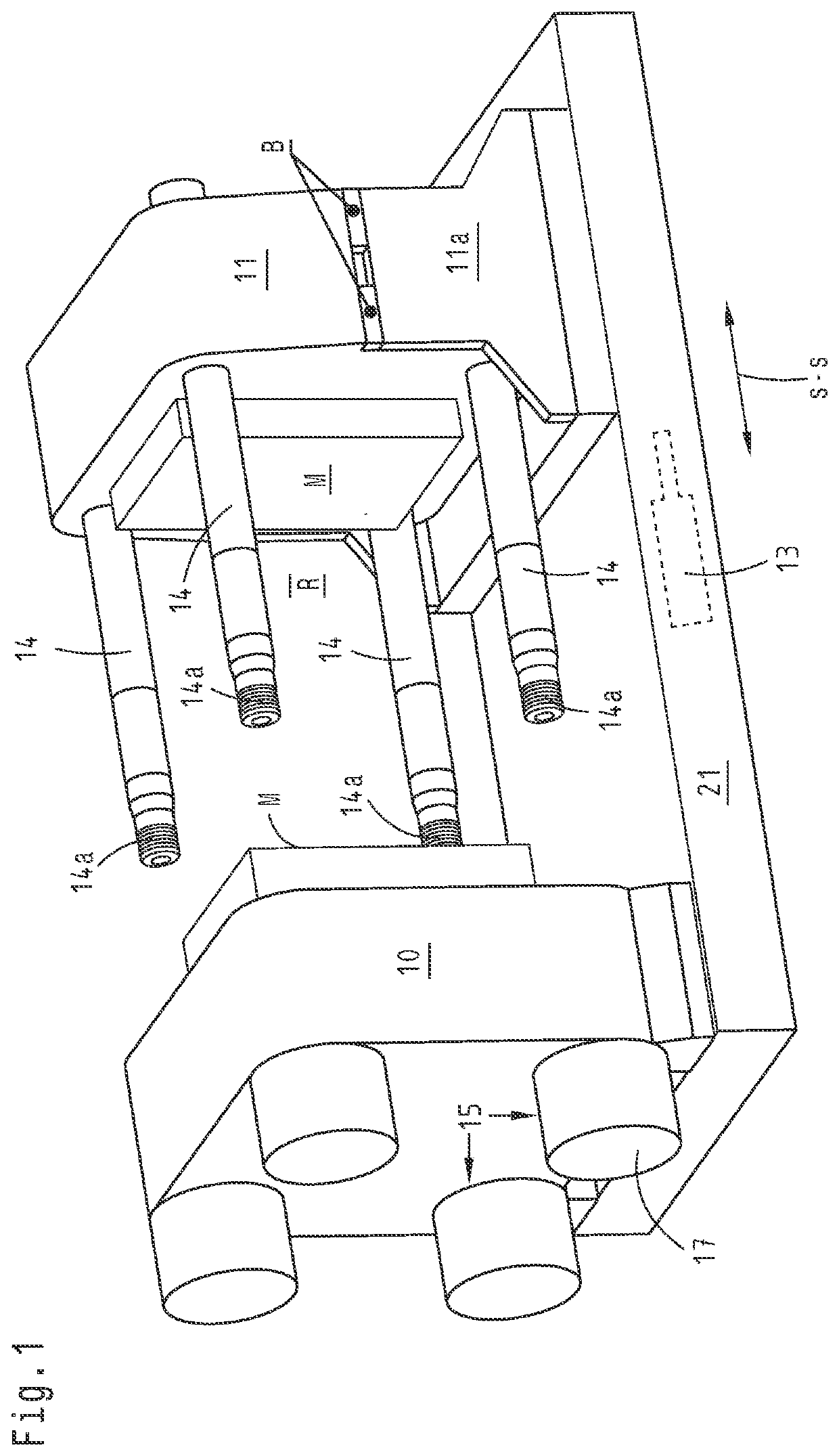
[0047]The Figures show a mold closing unit for an injection molding machine for processing plastics and other plasticizable materials. FIG. 1 shows a schematic representation of a mold closing unit of this kind ...


PUM

PropertyMeasurementUnit
closing forceaaaaaaaaaa
forceaaaaaaaaaa
pressureaaaaaaaaaa

Abstract

The invention relates to a mold-closing unit for an injection molding machine for processing plastics, comprising a mold-moving device for moving the movable mold support into and out of closure of an injection mold. At least one force transmission element is connected to the movable mold support and at its end remote from the movable mold support has a section (14a) which is assigned to the stationary mold support. The stationary mold support (10) is assigned a locking device (15) having a plurality of locking elements (70) which can be moved into interlocking operative connection with the actuatable section (14a). The locking device (15) has at least one actuator (16) which is movable in the closing direction (s-s) and on which, during movement of the actuator, the locking elements (70) are movable transversely to the closing direction (s-s) along a sliding block guide (60) in and out of an interlocking operative connection with the actuatable section (14a). The actuator is at the same time connected to at least one piston (18) of a piston-cylinder unit (17) for applying the closing force.

Description

CROSS REFERENCE TO RELATED APPLICATIONS[0001]The present application relates to and claims the priority of German patent application 10 2018 124 608.0 filed on Oct. 5, 2018, the disclosure of which is hereby explicitly incorporated by reference into the subject matter of the present application.TECHNICAL FIELD[0002]The disclosure relates to a mold closing unit for an injection molding machine for processing plasticizable materials, such as plastics, powdery or ceramic materials and to a method for locking a force transmission element to an injection molding machine.[0003]Within the scope of this application, the following terms are used as follows:[0004]The term “mold closure” of an injection mold is understood to mean the condition in which the parts of an injection mold that are secured to mold carriers of the injection molding machine abut against one another. This is typically the case when plasticized material is injected into the mold cavity of the injection mold. A travel mov...

Claims


Application Information

Patent Timeline
Patent Type & Authority Applications(United States)
IPC IPC(8): B29C45/67
CPCB29C45/6707B29C45/6728B29C45/68B29C2045/688
Inventor BLETSCHER, RAINER
Owner ARBURG GMBH & CO KG
Why Eureka
Try Eureka