
Double-sided printing apparatus

a printing apparatus and double-sided technology, applied in printing, typewriters, thin material processing, etc., can solve the problems of increasing the cost of cutting, increasing the cost of total production, and increasing the cost of continuous paper transportation, so as to reduce the possibility of dust generation or slowing down the feed speed of continuous paper, and simplify the transportation path of continuous paper. , the effect of reducing the cos

Inactive Publication Date: 2005-07-12
AVAYA TECH CORP +1
View PDF18 Cites 40 Cited by
  • Summary
  • Abstract
  • Description
  • Claims
  • Application Information

AI Technical Summary

Benefits of technology

[0015]It is the first object corresponding to the first task of the present invention to provide a double-sided printing apparatus at a relatively lower cost having little possibilities of dust generation or slowing feed speed of a continuous paper without complex mechanical structure nor control process by simplifying transportation path of the continuous paper from a first printer to a second printer.
[0016]It is the second object corresponding to the second task of the present invention to maintain a normal recording operation of a recording apparatus by preventing a user from forgetting to cleanup cutting dust in a dust stacker, the cutting dust generated from a cutting device.
[0017]It is the third object corresponding to the third task of the present invention to maintain normal printing quality by performing a minute transportation operation of a transporting roller even when a roll paper of increased weight is used.
[0018]It is the fourth object corresponding to the fourth task of the present invention to provide a transporting device removably installed on a recording apparatus for performing a printing job on a recording medium, where the transporting device includes a transporting roller, a slave transporting roller and a roller pressing device for providing pressing forces for closely contacting the transporting rollers with each other and can make the recording medium easily nipped between the transporting roller and the slave transporting roller.
[0040]Still another aspect of the present invention provides a double-sided printing apparatus further including a roll paper cassette, which can be removably installed on the double-sided printing apparatus, for setting the recording medium wound in a roll shape, wherein the roll paper cassette includes the paper transporting device.

Problems solved by technology

However, since the conventional double-sided printing system has the intermediate buffer device, the transportation path of the continuous paper between the first and second printers tends to be long and complex.
Therefore, total cost is increased.
In case the roll paper is manually cut, the cutting process requires human labor and edge profile is not desirable.
When the above described cutting device is installed on the conventional recording apparatus, unnecessary cutting dust is generated.
However, if the user leaves alone the dust stacker without discarding it, the cutting dust in the dust stacker can flow over to give bad effects to the recording apparatus.
Further, this problem is not only in the case of continuous paper but also in the case of discrete paper which is cut at a predetermined position.
The roll paper of increased weight has increased transporting load (or transportation load), so that paper transporting precision of a transporting roller or a sheet feed roller, which transports the continuous paper at a predetermined pitch, toward the recording unit is degraded, and the printing quality is also degraded.
However, the nipping job done by a user is not only complex and troublesome, but also incomplete.

Method used


Image

  • Double-sided printing apparatus
  • Double-sided printing apparatus
  • Double-sided printing apparatus

Examples


Embodiment Construction

[0079]Now, referring to attached drawings, embodiments of the present invention are described in detail.

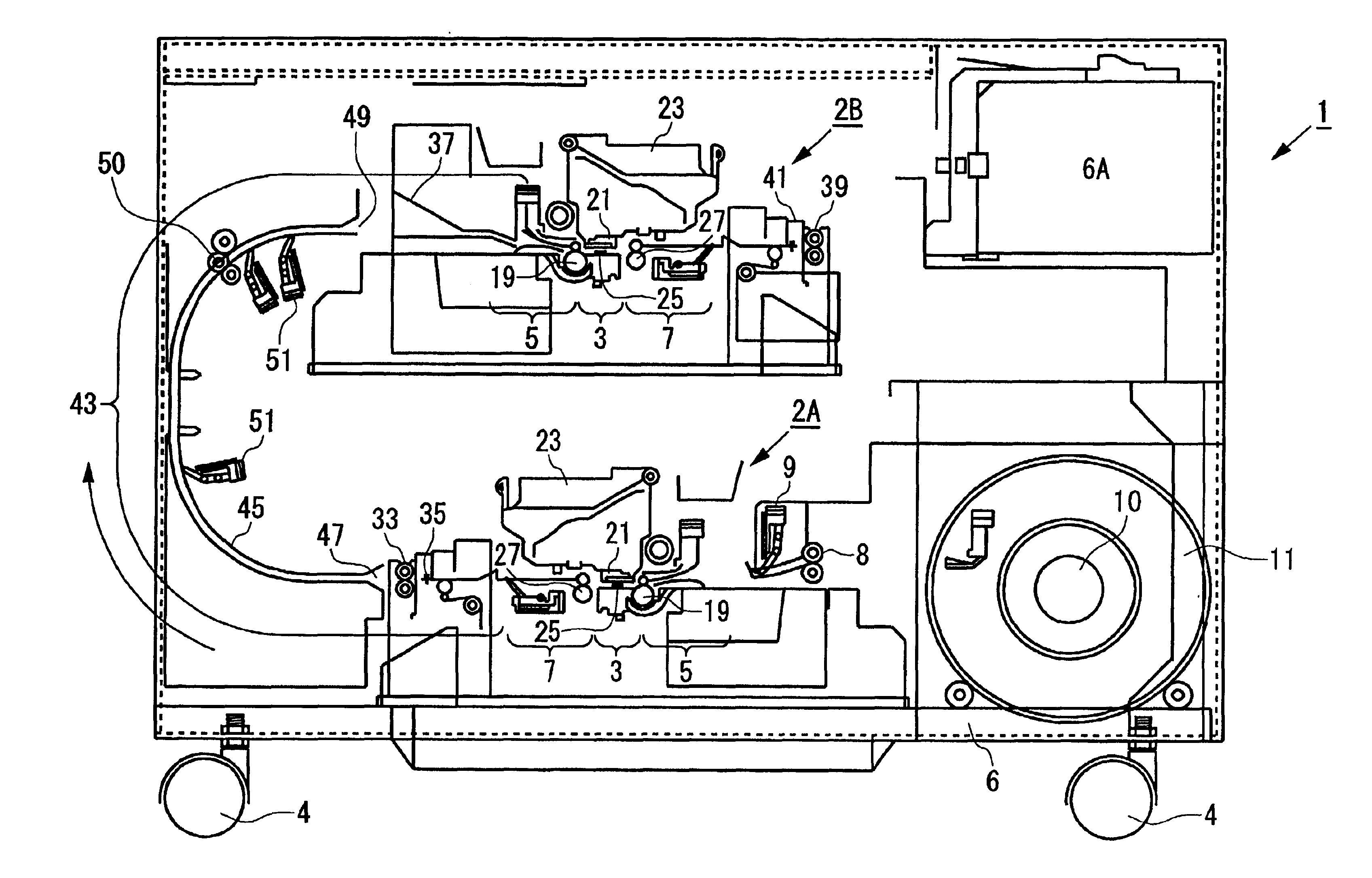
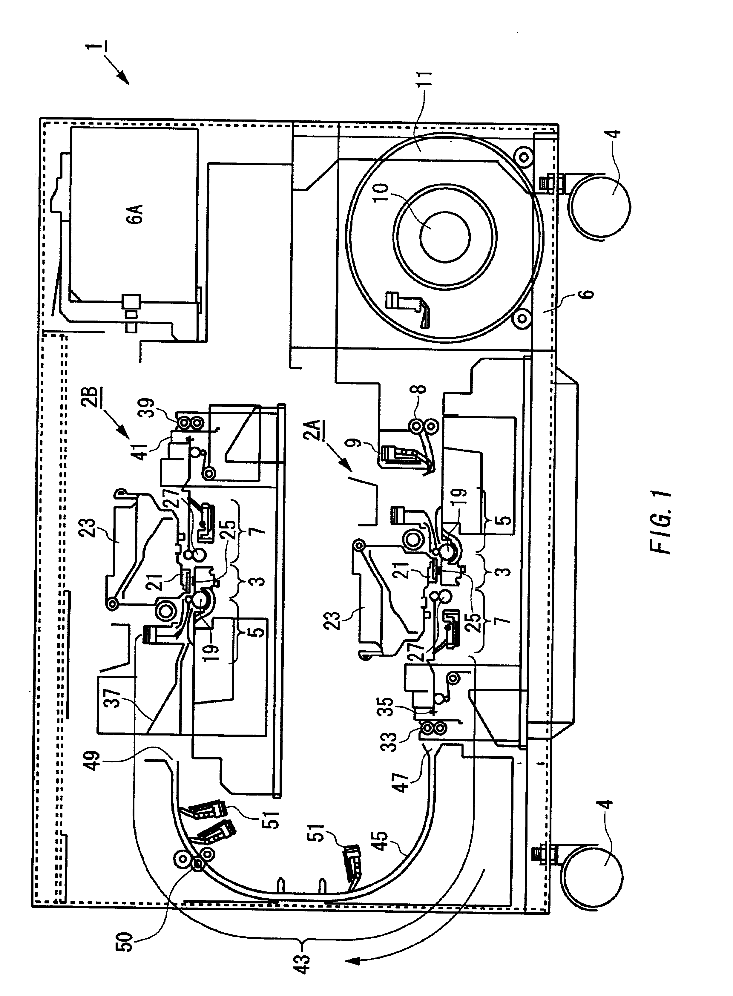
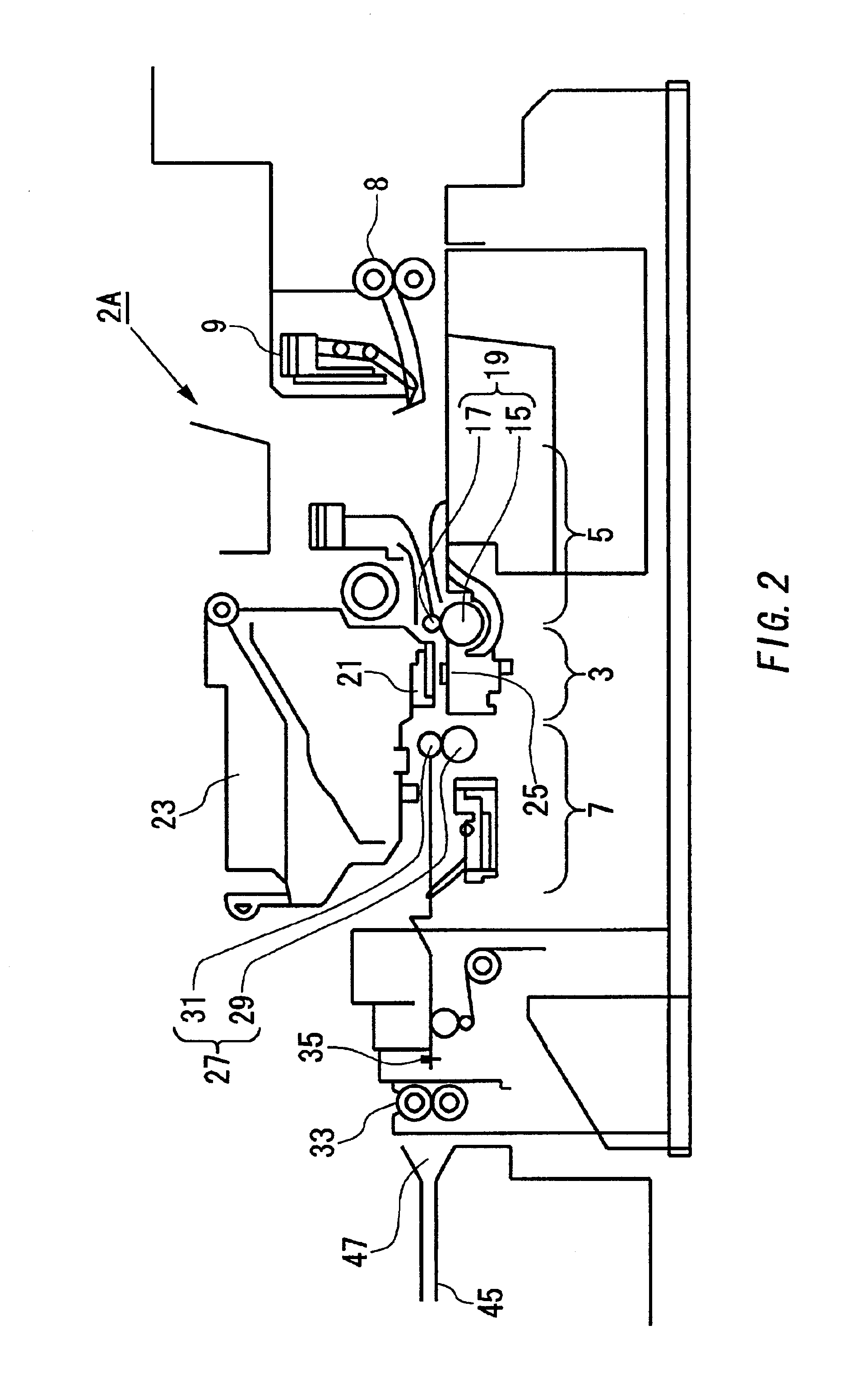
[0080]Now, referring to FIG. 1, FIG. 2 and FIG. 3, there are shown a cross-sectional side view of an embodiment of the double-sided printing apparatus of the present invention, an enlarged view of a first ink-jet printer and a cross-sectional side view of another embodiment of the double-sided printing apparatus of the present invention.

[0081]In FIG. 1, reference number 1 designates a double-sided printing apparatus of the present invention. The double-sided printing apparatus 1 includes a first and second ink-jet printers 2A and 2B disposed at a relatively lower and a relatively upper positions, respectively. The two ink-jet printers 2A and 2B are supported by a rest 6 having casts 4. In the rest 6, an ink cartridge 6A for providing ink to the ink-jet printers 2A and 2B is installed.

[0082]The first ink-jet printer 2A located at relatively lower position includes a printing sectio...


PUM


Abstract

The present invention is made to provide a double-sided printing apparatus at a relatively lower cost having little possibilities of dust generation or slowing feed speed of a continuous paper without complex mechanical structure nor control process, which includes: a first printer including a first transporting unit; a first recording unit disposed on upper or lower side of a transportation path of a recording medium, the recording medium being horizontally transported from the first transporting unit; and a first discharging unit for discharging the recording medium after printing; a second printer including a second transporting unit; a second recording unit disposed on upper or lower side of the transportation path of the recording medium horizontally transported from the first transporting unit, wherein the second recording unit is disposed on the same side where the first recording unit is disposed; and a second discharging unit for discharging the recording medium; and a guiding path disposed from the first discharging unit to the second discharging unit through which the recording medium printed by the first recording unit is guided, wherein surface of the recording medium is maintained in a plane while the recording medium is guided by the guiding path.

Description

[0001]This patent application claims priority from Japanese patent applications Nos. 2000-271086 filed on Sep. 7, 2000 and 2001-260385 filed on Aug. 29, 2001, the contents of which are incorporated herein by reference.BACKGROUND OF THE INVENTION[0002]1. Field of the Invention[0003]The present invention relates to a printing apparatus having a so-called “double-sided printing” function.[0004]2. Related Art[0005]According to a Japanese Patent Publication No. Hei. 7-237336, which is incorporated herein by reference, there is provided a conventional double-sided printing system which uses two (2) printers for printing on both faces of a continuous paper. An intermediate buffer device absorbing the paper feed speed difference between first and second printers is provided between the first and second printers, and a residence quantity detector detects residence quantity of the continuous paper in the intermediate buffer device. The conventional double-sided printing system is controlled a...

Claims


Application Information

Patent Timeline
Patent Type & Authority Patents(United States)
IPC IPC(8): B41J15/04B41J11/70B41J3/60B41J2/01B41J3/54B41J13/00B41J29/00B65H15/00B65H16/10B65H23/185B65H35/04
CPCB41J3/60B41J11/70B41J15/04
Inventor OTSUKA, KAZUOYOSHIDA, MASANORI
Owner AVAYA TECH CORP
Learn More