Inductively powered lamp assembly

a technology of inductively powered lamps and lamp assemblies, which is applied in the field of lighting, can solve the problems of spectral emitted loss, and achieve the effects of high power factor, simple and inexpensive, and high efficiency

Inactive Publication Date: 2005-07-12
PHILIPS IP VENTURES BV
View PDF58 Cites 344 Cited by
  • Summary
  • Abstract
  • Description
  • Claims
  • Application Information

AI Technical Summary

Benefits of technology

[0011]The present invention provides a simple and inexpensive lamp assembly for use with inductively powered lighting. Because the inductively powered lamp assembly operates at or near resonance, it has a high power factor and is highly efficient. This reduces power loss through heat build up and also provides for quiet operation of the inductive coupling—even in relatively high power applications. The efficiency of the secondary circuit demands less precise alignment between the primary and secondary, thereby permitting a greater degree of latitude in the layout and configuration of the lamp and the inductively powered lamp assembly. The sealed sleeve provides the lamp circuit with improved protection from the environment without limiting the transmission of light from the lamp. Although with some light sources, the spectrums emitted may see losses based on the specific transmissive properties of the materials used in the sleeves, for example, some materials are not highly transmissive to UV light. The present invention allows functional gases to be entrapped within the sealed sleeve to increase or reduce the degree to which the lamp is isolated from the environment. Further, by enclosing the entire lamp circuit within the lamp sleeve, the need for wires or electrical leads that penetrate the sleeve can be eliminated. This greatly improves the reliability of the lamp while dramatically reducing manufacturing losses. Also, the electromagnetic switch of the present invention provides an inexpensive and reliable alternative to conventional starter circuits.

Problems solved by technology

Although with some light sources, the spectrums emitted may see losses based on the specific transmissive properties of the materials used in the sleeves, for example, some materials are not highly transmissive to UV light.

Method used


Image

  • Inductively powered lamp assembly
  • Inductively powered lamp assembly
  • Inductively powered lamp assembly

Examples


Embodiment Construction

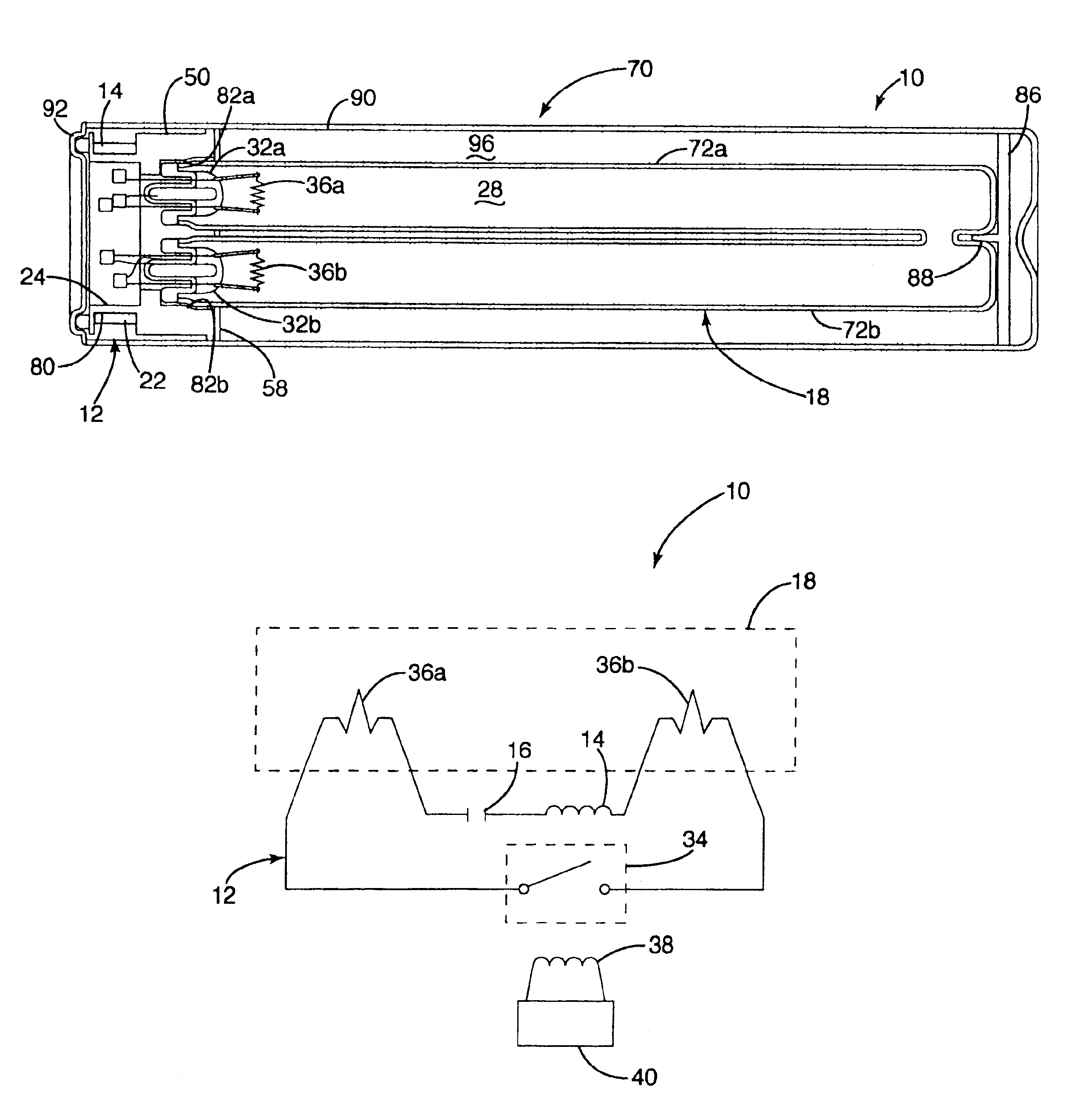
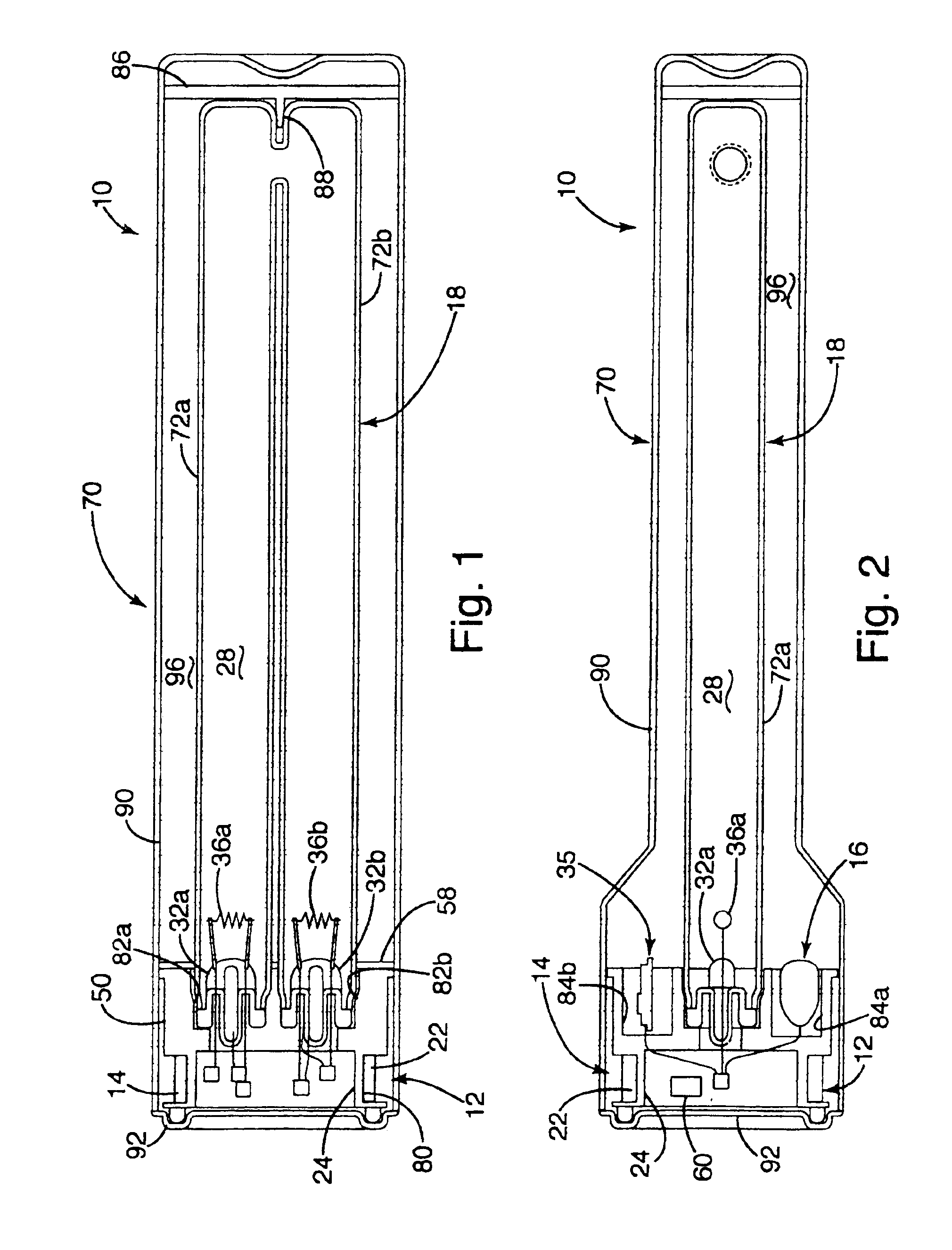
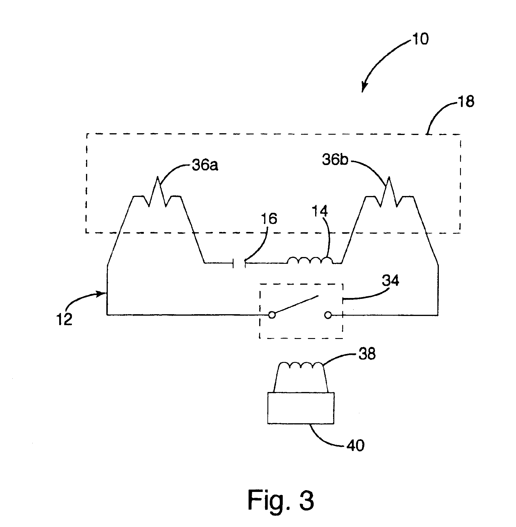
[0033]A lamp assembly according to an embodiment of the present invention is shown in FIGS. 1 and 2, and is generally designated 10. For purposes of disclosure, the present invention is first described in connection with a conventional type PL-S 11 watt UV lamp converted for use at 38 watt, such as the type used in a water treatment device. The inductively powered lamp assembly 10 generally includes a lamp circuit 12 and an outer sleeve 70. The lamp circuit 12 includes a secondary 14, a capacitor 16 and a lamp 18, all connected in series (See FIG. 3). The secondary 14 inductively receives power from the primary (not shown) of an associated ballast (not shown). The series capacitor 16 is specially tuned, as described in more detail below, so that the lamp circuit operates at resonance under specific operating conditions. The entire lamp circuit 12 is fully enclosed within the outer sleeve 70, including the secondary 14, capacitor 16 and lamp 18. At least a portion of the outer sleeve...


PUM

PropertyMeasurementUnit
poweraaaaaaaaaa
power factoraaaaaaaaaa

Abstract

A lamp assembly configured to inductively receive power from a primary coil. The inductively powered lamp assembly includes a lamp circuit including a secondary and a lamp connected in series. In a first aspect, the lamp circuit includes a capacitor connected in series with the lamp and the secondary to tune the circuit to resonance. The capacitor is preferably selected to have a reactance that is substantially equal to or slightly less than the reactance of the secondary and the impedance of the lamp. In a second aspect, the inductively powered lamp assembly includes a sealed transparent sleeve that entirely encloses the lamp circuit so that the transparent sleeve is fully closed and unpenetrated. The transparent sleeve is preferably the lamp sleeve itself, with the secondary, capacitor and any desired starter mechanism disposed within its interior.

Description

[0001]The present invention is a continuation of U.S. application Ser. No. 10 / 133,860, which was filed on Apr. 26, 2002 which is now U.S. Pat. No. 6,731,071, which is a continuation-in-part of U.S. application Ser. No. 09 / 592,194 entitled “Water Treatment System with an Inductively Coupled Ballast,” which was filed on Jun. 12, 2000 (now U.S. Pat. No. 6,436,299).BACKGROUND OF THE INVENTION[0002]The present invention relates to lighting and more particularly to a lamp assembly for use in connection with inductively powered lighting.[0003]Although not widely available, inductively coupled lighting systems are known. A conventional inductively coupled lighting system generally includes a primary circuit having a primary coil (or “primary”) that is driven by a power supply and a secondary circuit having a secondary coil (or “secondary”) that inductively receives power from the primary. Inductive couplings provide a number of advantages over conventional direct electrical connections. Fir...

Claims


Application Information

Patent Timeline
Patent Type & Authority Patents(United States)
IPC IPC(8): A61L2/10C02F9/00C02F1/32H05B37/00H05B37/03H05B39/00H05B41/36H05B41/24C02F1/28F21S2/00F21Y101/00F21Y103/37H01J5/52H01J61/56H01K1/18H05B1/00H05B41/10
CPCA61L2/10C02F1/325C02F9/005H01F38/14H01J5/50H01J5/52H01J5/54H01J61/56H01K1/44H01K1/46H05B37/03H05B39/00H05B41/10H05B41/24H05B41/295H05B41/36Y02B20/19B01D2201/34C02F1/283C02F1/32C02F2201/006C02F2201/3222C02F2201/3228C02F2201/326B01D2201/301F21W2131/103H05B47/25C02F9/20H05B41/16H01J13/46F21V23/00Y02B20/00
Inventor BAARMAN, DAVID W.
Owner PHILIPS IP VENTURES BV
Why Eureka
Try Eureka