Fluid dispenser pump

a dispenser pump and fluid technology, applied in the direction of instruments, volume meters, single-unit devices, etc., can solve the problems of pump failure, pump inconvenient operation, pump inlet valve to open early,

Inactive Publication Date: 2005-07-19
APTAR FRANCE SAS
View PDF5 Cites 12 Cited by
  • Summary
  • Abstract
  • Description
  • Claims
  • Application Information

AI Technical Summary

Benefits of technology

[0004]An object of the present invention is to provide a manually-actuated fluid dispenser pump that does not suffer from the above-mentioned drawbacks.
[0005]Thus, an object of the present invention is to provide such a dispenser pump that makes it possible to vary the radial stresses exerted on the pistons of the pump between their respective rest and dispensing positions.
[0006]An object of the present invention is also to provide such a fluid dispenser pump that guarantees that a dose of fluid is expelled accurately and reproducibly every time the pump is actuated.
[0007]An object of the invention is also to provide such a dispenser pump that is simple and inexpensive to manufacture and to assemble.
[0009]Advantageously, said piston is mounted to slide in a pump body portion between the rest position and the dispensing position, the inside diameter of said pump body portion that co-operates with said piston in the rest position being larger than the inside diameter of said pump body portion that co-operates with said piston in the dispensing position, so that the radial stresses exerted by the pump body on said piston are smaller in the rest position.
[0013]Advantageously, said piston is mounted to slide in a pump body portion between a rest position and a dispensing position, the inside diameter of said pump body portion that co-operates with said piston in the rest position being smaller than the inside diameter of said pump body portion that co-operates with said piston in the dispensing position, so that the radial stresses exerted by the pump body on said piston are larger in the rest position.

Problems solved by technology

Unfortunately, most pumps are used at irregular intervals, and the pump spends most of its time in the rest position.
The high radial stresses that are exerted on the piston, also when it is in the rest position, can be disadvantageous in that ultimately they can damage the sealing lips of the piston or can deform them, thereby diminishing their leaktightness, which can cause the pump to malfunction.
For the second piston, there is a risk that, when it returns from its dispensing position to its rest position, i.e. generally during the stage in which the fluid contained in the pump chamber is expelled, the suction generated by said expulsion inside the pump chamber might cause the inlet valve of the pump to open early, or might cause the outlet valve of the pump chamber to close early, when valve opening and closure is controlled by said second piston.
However, that requires a larger actuating force to actuate the pump.
Such malfunctioning of the valves of the pump chamber can result in non-uniform quantities or “doses” of fluid being dispensed because the times at which said valves open and close are no longer accurately predeterminable and reproducible each time the pump is actuated.

Method used


Image

  • Fluid dispenser pump
  • Fluid dispenser pump
  • Fluid dispenser pump

Examples


Embodiment Construction

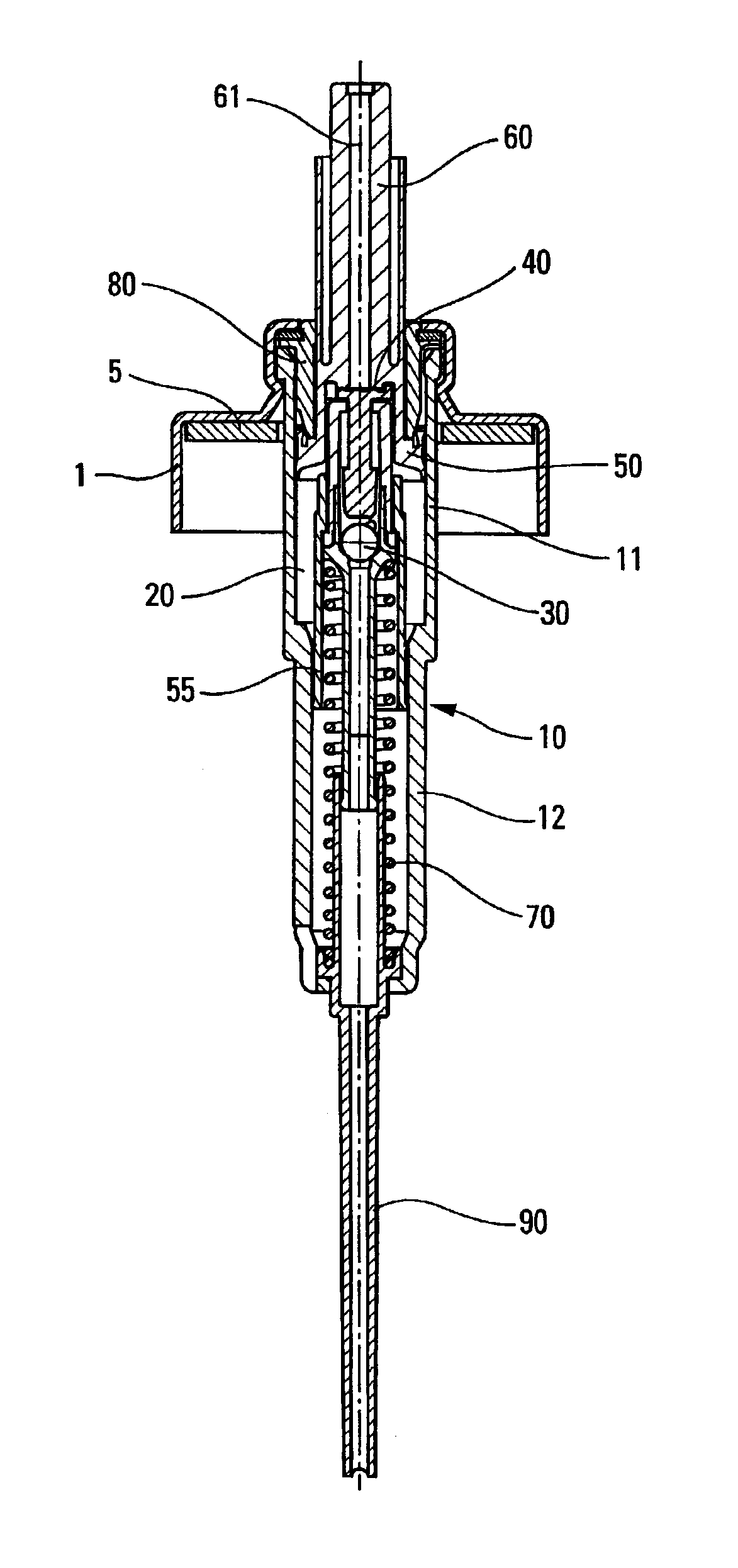
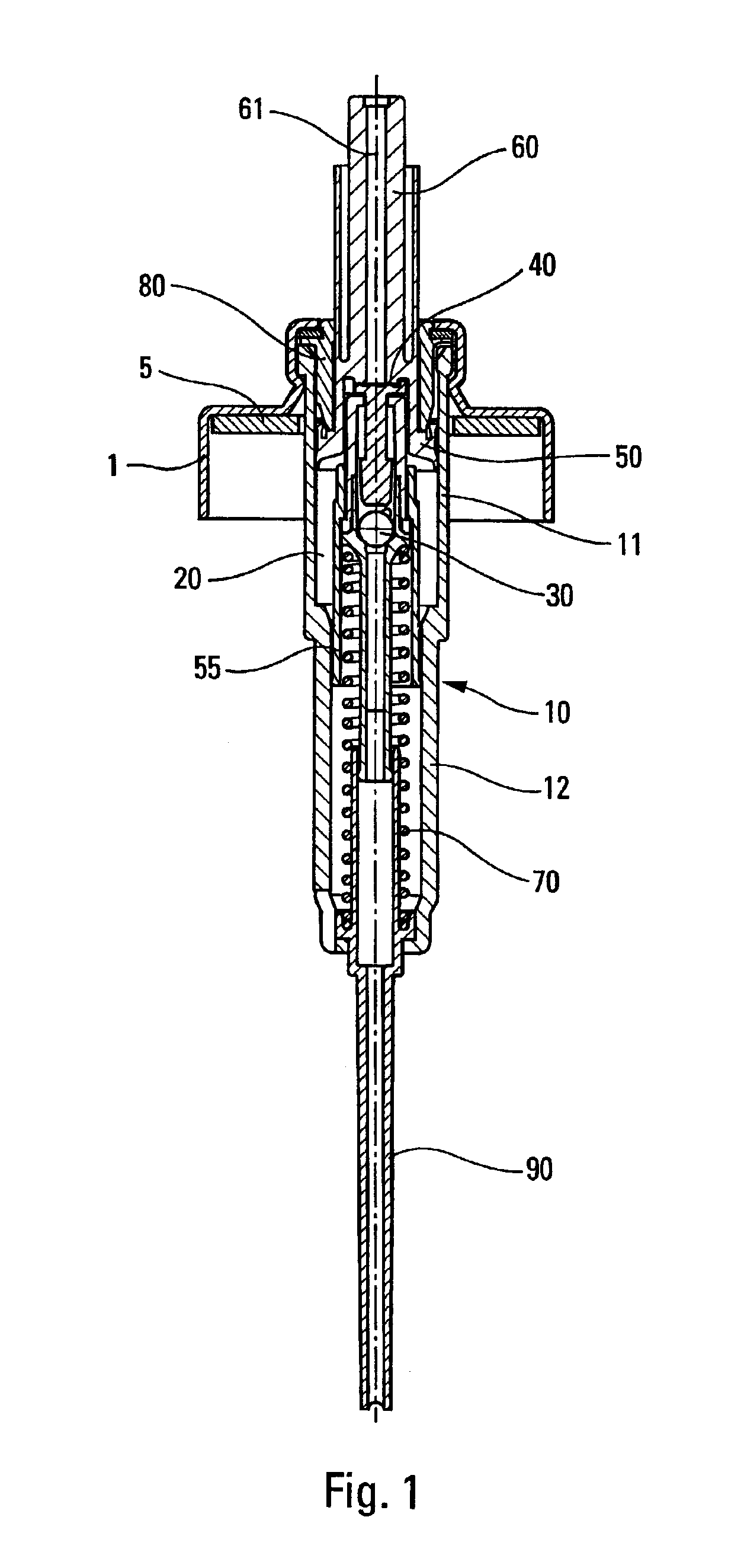
[0024]FIG. 1 shows a pump including a pump body 10 in which a first piston 50 and a second piston 55 are mounted to slide between respective rest and dispensing positions. The present invention is described below with reference to this particular pump, but it is to be understood that the invention is not limited to the pump shown in FIG. 1. On the contrary, the present invention is applicable to any fluid dispenser pump in which at least one piston is mounted to slide in a pump body. More precisely, although in the pump of FIG. 1, the present invention incorporates two distinct pump body portions with two pistons, each of which implements the present invention, it is quite possible to apply the present invention to pumps having one piston only, or having two pistons but in which only one of said pistons is mounted to slide in a pump body incorporating the present invention.

[0025]The pump shown in FIG. 1 thus includes a pump body 10 provided with a first pump body portion 11 in which...


PUM


Abstract

A manually-actuated fluid dispenser pump including a pump body (10) and at least one piston (50, 55) mounted to slide in leaktight manner in said pump body (10) between a rest position and a dispensing position, said pump being characterized in that the pump body (10) is frustoconical at least in part so as to modify the radial stresses exerted on said at least one piston (50, 55) between said rest position and said dispensing position.

Description

CROSS REFERENCE TO RELATED APPLICATION[0001]This application claims the benefit under 35 U.S.C. §119(e) of U.S. provisional patent application Ser. No. 60 / 387,432, filed Jun. 11, 2002, now abandoned, and priority under 35 U.S.C. §119(a)-(d) of French patent application No. FR-02.05251, filed Apr. 19, 2002.TECHNICAL FIELD[0002]The present invention relates to a manually-actuated fluid dispenser pump, and to a fluid dispenser device including such a pump.BACKGROUND OF THE INVENTION[0003]In known manner, a fluid dispenser pump generally includes a pump body in which a piston is mounted to slide between a rest position and a dispensing position. The pump body is cylindrical and the end positions of the piston, namely the rest position and the dispensing position, are defined by various means, e.g. abutment means. When the pump is actuated, the pump chamber is filled with fluid, and the leaktightness constraints for the piston while it is moving inside the pump body are very stringent to...

Claims


Application Information

Patent Timeline
Patent Type & Authority Patents(United States)
IPC IPC(8): B05B11/00G01F11/02
CPCB05B11/3001B05B11/3019B05B11/304G01F11/028B05B11/1019B05B11/1001B05B11/104
Inventor PETIT, LUDOVIC
Owner APTAR FRANCE SAS
Why Eureka
Try Eureka