Ultra-wideband imaging system

a wide-band imaging and ultra-wideband technology, applied in the field of imaging systems, can solve the problems of low field strength of permanent magnet mris, low field strength of resistive mri, and high operational cost and low field stability

Inactive Publication Date: 2005-07-19
INTELLECTUAL VENTURES HOLDING 81 LLC
View PDF8 Cites 142 Cited by
  • Summary
  • Abstract
  • Description
  • Claims
  • Application Information

AI Technical Summary

Problems solved by technology

Resistive MRI is inexpensive but does not have high field strength.
Additionally, it has high operational cost and low field sta

Method used


Image

  • Ultra-wideband imaging system
  • Ultra-wideband imaging system
  • Ultra-wideband imaging system

Examples


Embodiment Construction

[0013]In the following paragraphs, the present invention will be described in detail by way of example with reference to the attached drawings. Throughout this description, the preferred embodiment and examples shown should be considered as exemplars, rather than as limitations on the present invention. As used herein, the “present invention” refers to any one of the embodiments of the invention described herein, and any equivalents. Furthermore, reference to various feature(s) of the “present invention” throughout this document does not mean that all claimed embodiments or methods must include the referenced feature(s).

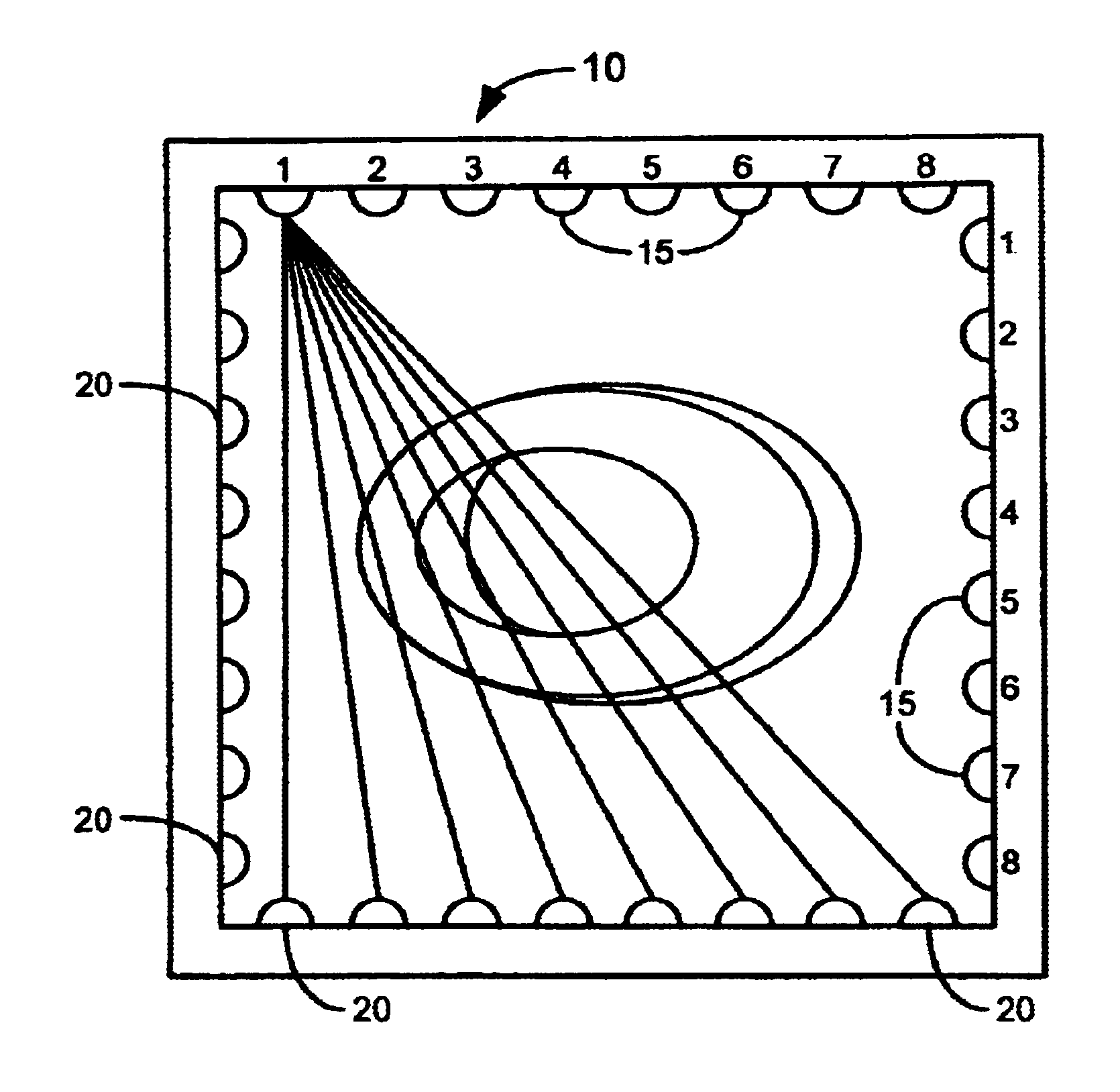
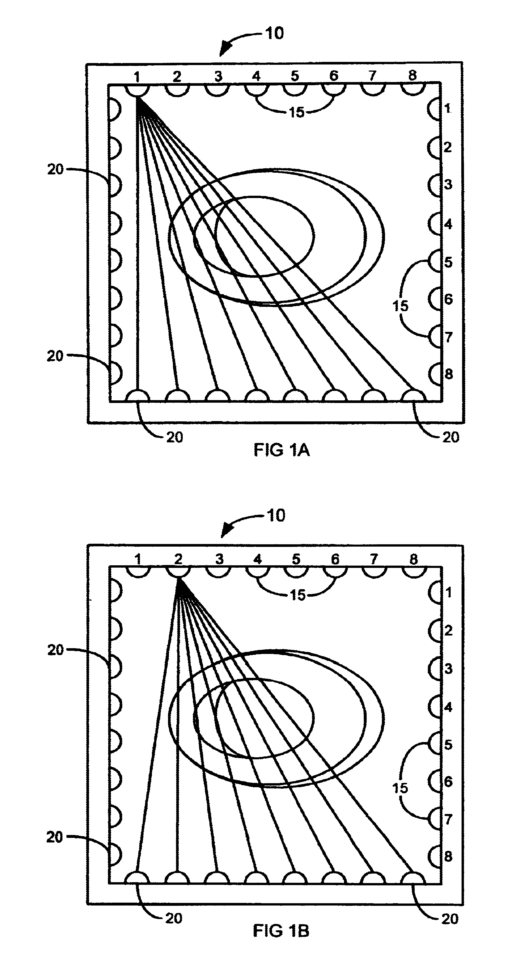
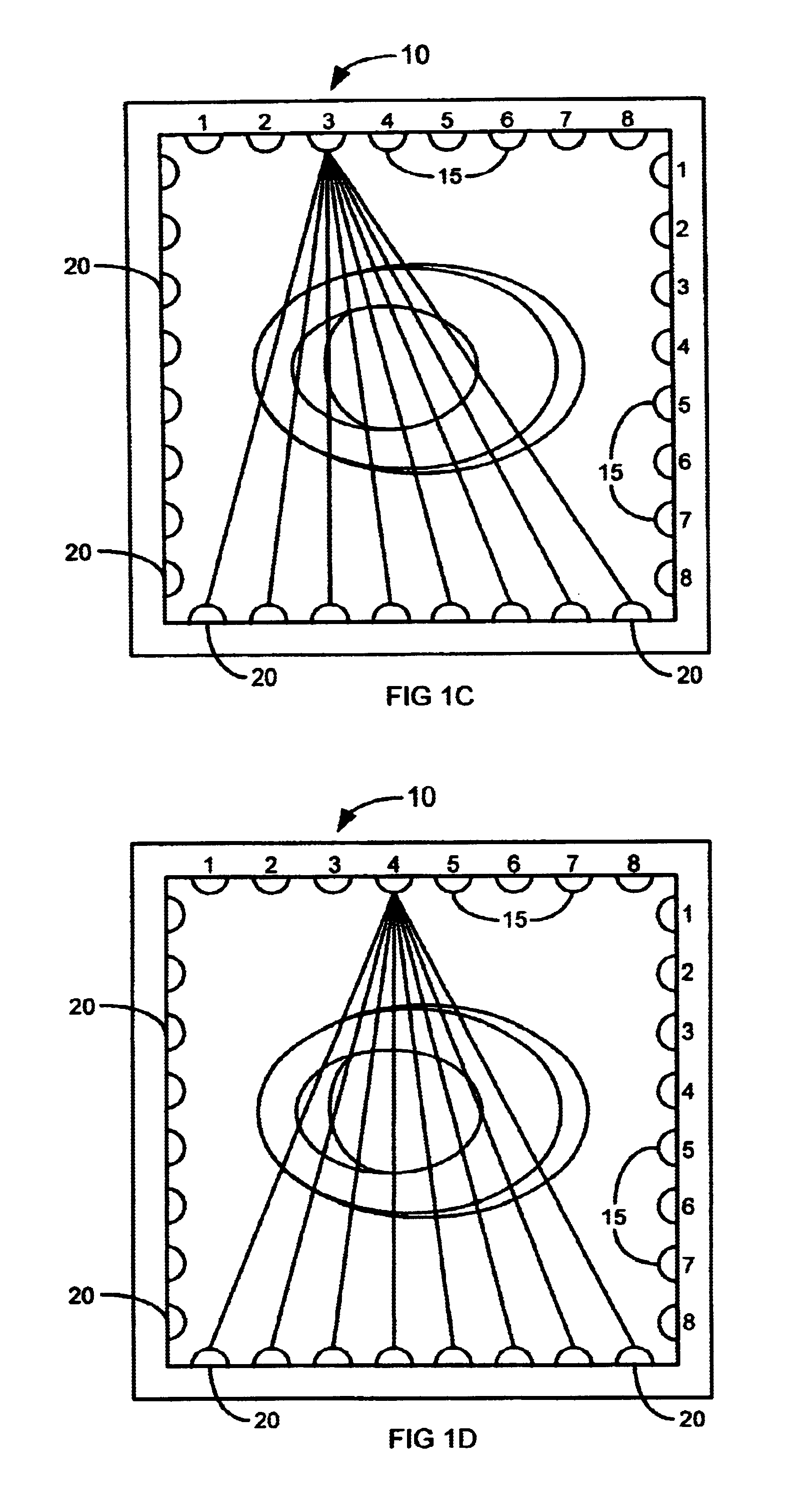
[0014]The present invention is directed to a scanning and imaging system, method and apparatus that employs at least one ultra-wideband (UWB) emitter, or transmitter. One embodiment of the present invention transmits UWB pulses that include “sub-harmonic frequencies” similar to the atomic frequencies of pre-cancerous cell molecules. The cells receive the energy, and ...


PUM


Abstract

The present invention comprises a scanner or imager that employs a plurality of ultra-wideband (UWB) transmitters that emit a multiplicity of UWB pulses, which are received by a plurality of receivers. An object or person positioned between the UWB transmitters and receivers can be scanned and subsequently imaged in extreme detail, due to the broad spectral content of the UWB pulses. The UWB scanner can be constructed as a stationary or portable device.

Description

[0001]Priority is claimed to U.S. Provisional Application Ser. No. 60 / 338,395, filed Nov. 9, 2001, titled “Ultra-Wideband Imaging System,” which is referred to and incorporated herein in its entirety by this reference.FIELD OF THE INVENTION[0002]The present invention generally relates to imaging systems. More particularly the invention concerns an imaging system that employs ultra-wideband technology.BACKGROUND OF THE INVENTION[0003]A variety of scanning and imaging systems are employed for uses ranging from airport security to biomedical imaging. Some of these systems employ technologies including X-rays, Magnetic Resonance Imaging (MRI), and Nuclear Quadrupole Resonance (NQR). Essentially, there are three types of MRI: Superconductive, Resistive, and Permanent. Superconductive. MRI provides high field strength, but requires constant liquid helium replenishment. Resistive MRI is inexpensive but does not have high field strength. Additionally, it has high operational cost and low fi...

Claims


Application Information

Patent Timeline
IPC IPC(8): A61B5/00G01S13/02G01S13/89
CPCA61B5/0059G01S13/0209G01S13/89
Inventor SANTHOFF, JOHN H.
Owner INTELLECTUAL VENTURES HOLDING 81 LLC
Why Eureka
Try Eureka