Average volume ventilation

a technology of ventilation and volume, applied in the field of ventilators, can solve the problems of large changes in the volume of fluid delivered to the patient, unnatural variation in the volume of fluid, and discomfort for spontaneous breathing patients, and achieve the effect of reducing the difficulty of ventilating

Inactive Publication Date: 2005-07-26
RIC INVESTMENTS LLC
View PDF10 Cites 174 Cited by
  • Summary
  • Abstract
  • Description
  • Claims
  • Application Information

AI Technical Summary

Benefits of technology

[0008]Accordingly, it is an object of the present invention to provide a ventilator and method of controlling a ventilator that overcomes the shortcomings of conventional ventilators and conventional modes of ventilation. This object is achieved according one embodiment of the present invention by providing a method for adjusting a volume of fluid supplied to a patient from one inhalation to the next in a manner that is comfortable for the patient and responsive to the patient's changing respiratory demands. This method includes supplying a plurality of volumes of fluid to a patient during a like plurality of inspiratory phases of the patient. Each volume of fluid is supplied at an inspiratory positive airway pressure (“IPAP”) during a corresponding inspiratory phase, which is either triggered by the patient or by the ventilator. For each inspiratory phase, a volume of fluid received by the patient is determined. An average volume of fluid received by the patient is determined by taking an average of the volumes of fluid received by the patient during the plurality of inspiratory phases. The average volume of fluid received by the patient is compared to a predetermined target volume and the inspiratory positive airway pressure is adjusted based on this comparison.
[0014]The above object of providing a ventilator that overcomes the shortcomings of conventional ventilators is accomplished according to one embodiment of the present invention by providing an apparatus for supplying fluid to a patient that includes a pressure generating system that provides a flow of fluid at a variable pressure or a variable flow. A patient circuit operatively coupled to the pressure generating system delivers the flow of fluid to a patient. An interface device coupled to the patient circuit communicates the flow of fluid to the airway of the patient. At least one sensor in the apparatus detects a parameter indicative of a volume of fluid delivered to the patient. In addition, a controller receives signals from the sensor and controls the pressure generating system. In particular, the controller (a) determines, for each inspiratory phase of a respiratory cycle of the patient, a volume of fluid received by the patient based on the parameter indicative of a volume of fluid delivered to the patient provided by the sensor, (b) determines an average volume of fluid received by the patient over a plurality of inspiratory phases, (c) compares the average volume of fluid received by the patient to a predetermined target volume, and (d) causes the pressure generating system to adjust the pressure or the rate of flow of fluid output thereby based on this comparison.

Problems solved by technology

A problem with adjusting the volume of fluid delivered for one inhalation based upon a difference between the volume of fluid delivered during a previous inhalation and the target volume of fluid is that large differences between the previous volume and the target volume can result in large changes in the volume of fluid delivered to the patient.
Such changes can result in the patient experiencing uncomfortable and unnatural variations in the volume of fluid received from one inhalation to another.
Because this increase in pressure typically occurs near the end of the breath, when the patient is most likely to want to exhale, this mode of ventilation can be uncomfortable to the spontaneously breathing patient.

Method used


Image

  • Average volume ventilation
  • Average volume ventilation
  • Average volume ventilation

Examples


Embodiment Construction

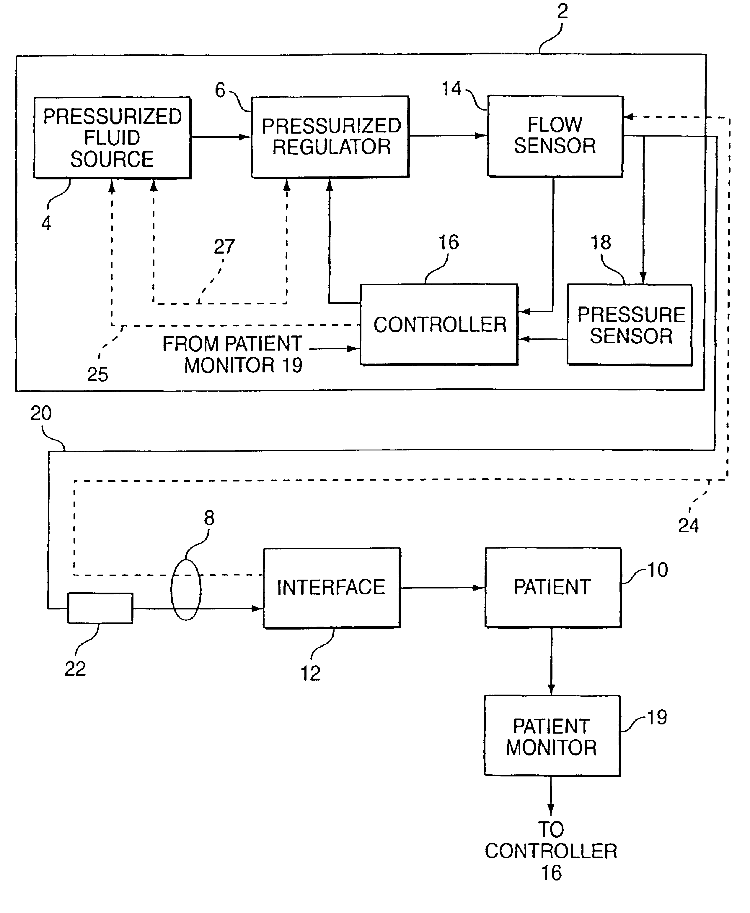
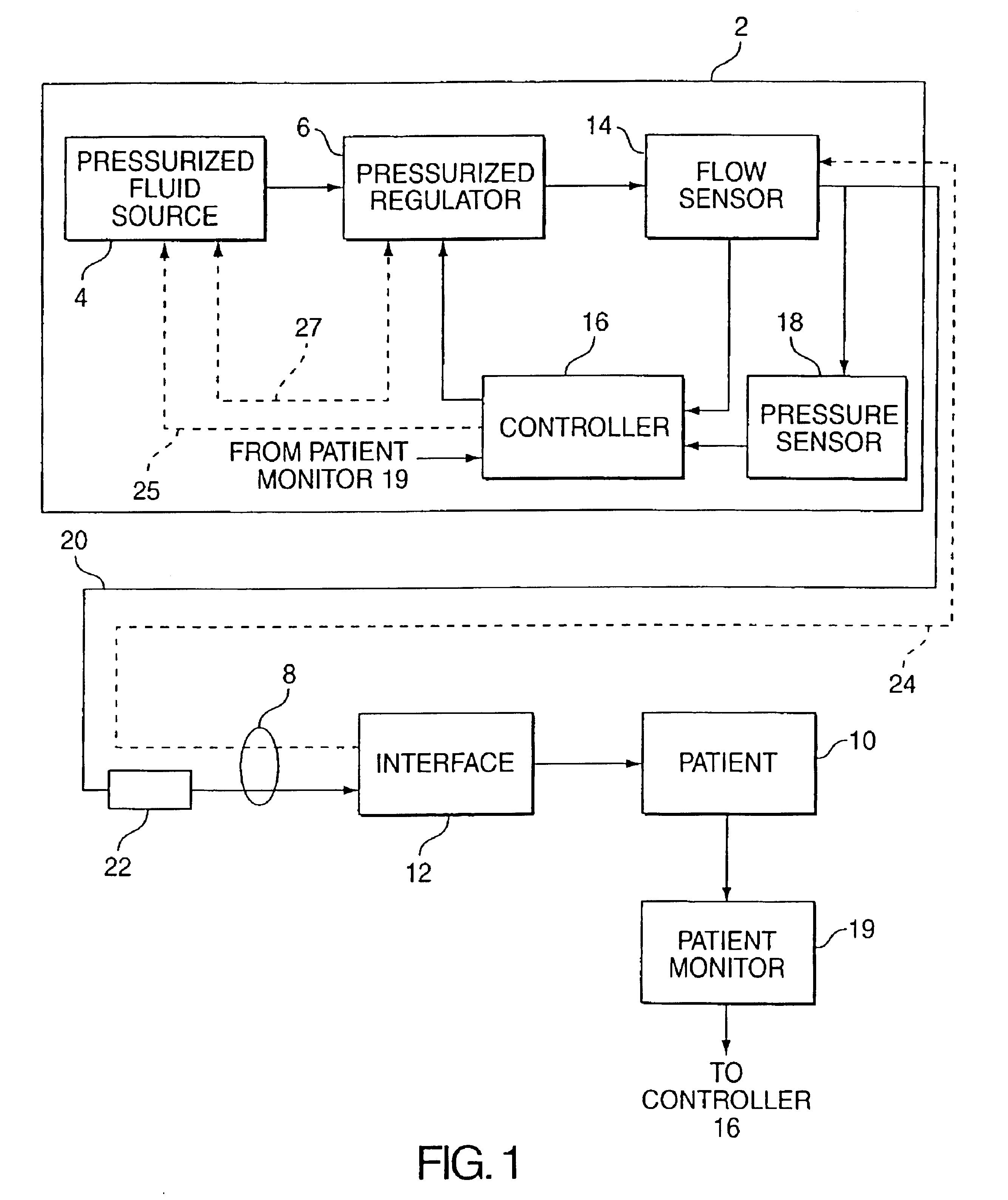
[0022]FIG. 1 illustrates an exemplary embodiment of a pressure support system or ventilator 2 according to the principles of the present invention. As used herein, the term “ventilator” refers to any device that delivers a flow of breathing gas to a patient at a variable pressure, and is not intended to be limited to a life support ventilating system. An example of a pressure support system that provides a variable pressure to the patient based on patient's respiratory cycle that is not necessarily used for life support purposes is the pressure support system taught in U.S. Pat. Nos. 5,148,802 and 5,433,193, both to Sanders et al., the contents of which are incorporated by reference into the present application.

[0023]Ventilator 2 includes a source of pressurized fluid 4 and a pressure regulator 6 connected to receive pressurized fluid from source of pressurized fluid 4. Pressure regulator 6 regulates the pressure of the pressurized fluid supplied to a patient circuit 8, which convey...


PUM


Abstract

A ventilator supplies a plurality of volumes of fluid to a patient during a like plurality of inhalations by the patient. Each volume of fluid is supplied at an inspiratory positive airway pressure during a corresponding inhalation by the patient. A volume of fluid received by the patient is determined for each of the plurality of inhalations by the patient and an average volume of fluid received by the patient during each of the plurality of inhalations is determined. The average volume of fluid received by the patient during each inhalation is compared to a predetermined target volume and the inspiratory positive airway pressure each volume of fluid is supplied to the patient is adjusted as a function of the comparison.

Description

CROSS-REFERENCE TO RELATED APPLICAIONS[0001]This application claims priority under 35 U.S.C. § 119(e) from U.S. provisional patent application No. 60 / 139,424 filed Jun. 15, 1999.BACKGROUND OF THE INVENTION[0002]1. Field of the Invention[0003]The present invention pertains to a ventilator and a method of controlling a ventilator to supply a desired inspiratory target volume of fluid, such as air or an oxygen mixture, to a patient.[0004]2. Description of the Related Art[0005]It is known to utilize a conventional ventilator to deliver a fluid, such as air or an oxygen mixture, to a patient in a volume targeted ventilation mode in which the ventilator attempts to deliver to the patient, during inspiration, a preset volume of fluid. To adjust the volume of fluid delivered to the patient during inspiration to achieve this target volume during each inspiration, the ventilator adjusts the pressure of the fluid supplied to the patient. For example, for a given inspiratory phase in a pluralit...

Claims


Application Information

Patent Timeline
Patent Type & Authority Patents(United States)
IPC IPC(8): A61M16/00
CPCA61M16/00A61M2016/0021A61M2016/0027A61M2016/0039A61M2205/15A61M2230/60A61M16/026
Inventor HILL, PETER D.KISSEL, MICHAEL H.FRANK, JOHN
Owner RIC INVESTMENTS LLC
Why Eureka
Try Eureka