
Mask defogging system and method

Inactive Publication Date: 2005-07-26
ZAHRT JUSTIN W +1
View PDF13 Cites 9 Cited by
  • Summary
  • Abstract
  • Description
  • Claims
  • Application Information

AI Technical Summary

Benefits of technology

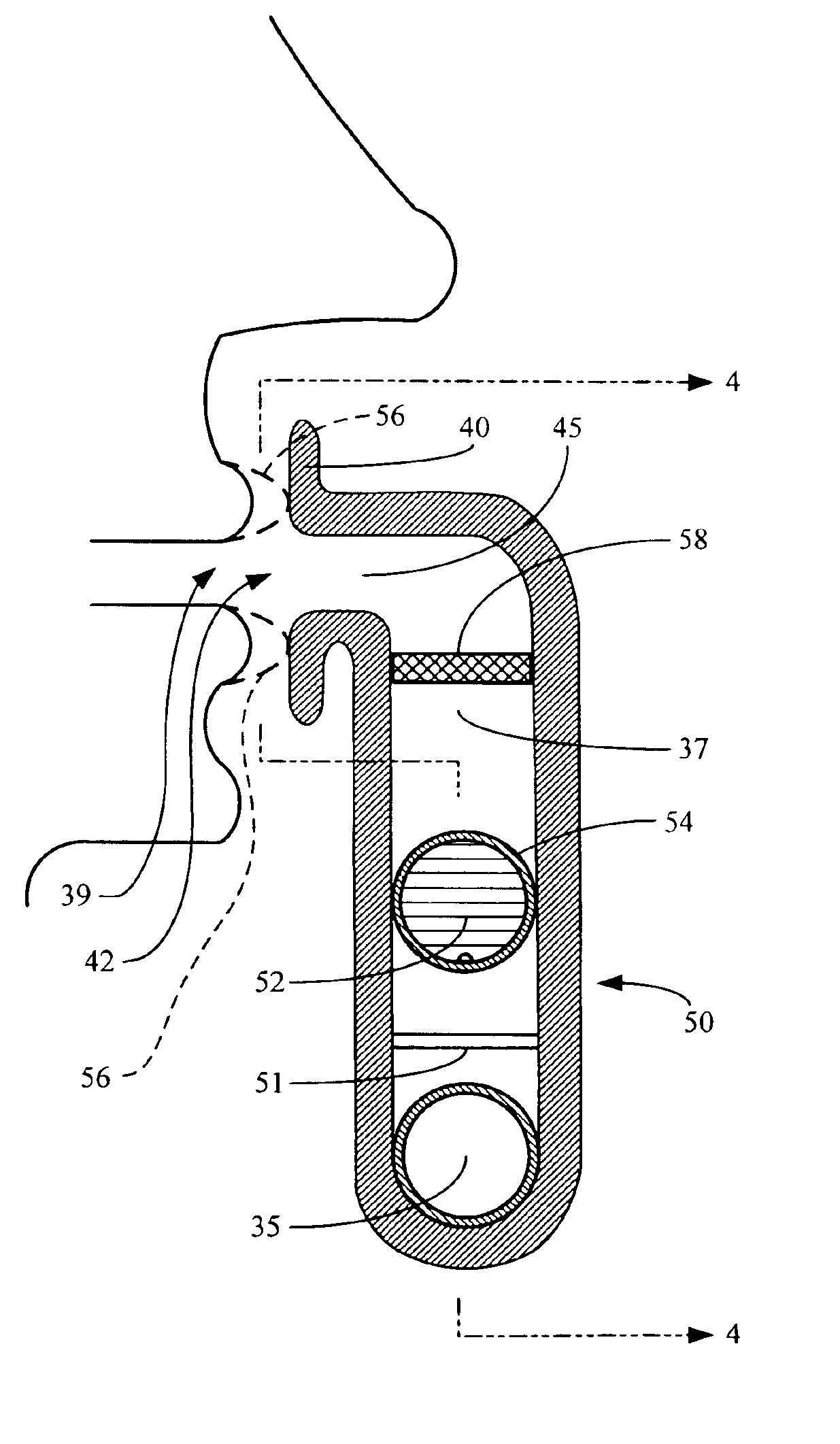
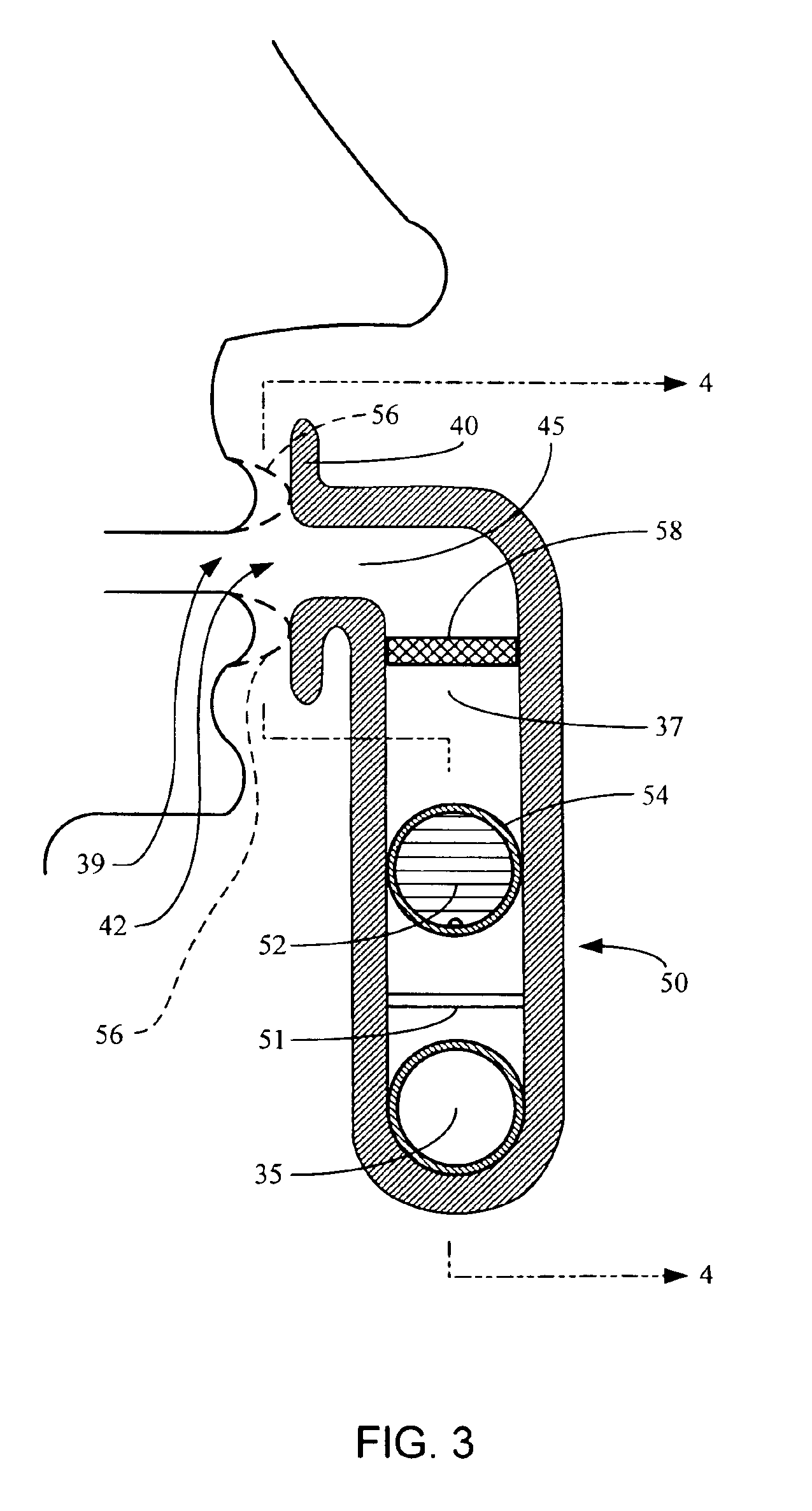
[0012]The present invention provides a method for purging air in the goggle area on the interior of a face mask. A mouthpiece is positioned in a service position immediately in front of the mouth of a person wearing such a face mask such that the person can selectively engage an airway in the mouthpiece by puckering the person's lips thereagainst. Positive purging of air in the goggle area on the interior of the face mask is assured by permitting air to flow from the goggle area on the interior of the face mask to the mouthpiece airway while substantially preventing air flow in the opposite direction. Air from the goggle area on the interior of the face mask is purged through the mouthpiece by affirmative, breath-driven, passive ventilation while permitting a person wearing the face mask to breathe freely and without distraction, obstruction, or deliberate action, by normal breathing with the lips in a natural position just behind the mouthpiece. Increased ventilation for the goggle area on the interior of the face mask is selectively forced by puckering the person's lips to engage the mouthpiece while not requiring support or retention of the mouthpiece manually or with the lips or teeth.

Problems solved by technology

Fog formation on the eye-protecting goggles of face masks has long been a problem.
The major difficulty is the limited ventilation in the small space that protects and surrounds the eye area of the wearer.
Unfortunately, there is still a need to improve such mask defogging designs.
For example, powered systems can be uncomfortably heavy.
In addition, powered systems can be loud, preventing good hearing.
Furthermore, anti-fog coatings can degrade, especially after repeated washing and cleaning.
Increased respiration in such cases is also incompatible with “active” ventilation systems since defogging the mask requires action by the wearer.
Many people, such as paintball players and motorcycle riders, have already invested in very expensive masks and helmets.
Solutions to these problems have been long sought but prior developments have not taught or suggested any solutions and, thus, solutions to these problems have long eluded those skilled in the art.

Method used


Image

  • Mask defogging system and method
  • Mask defogging system and method
  • Mask defogging system and method

Examples


Embodiment Construction

[0018]In the following description, numerous specific details are given to provide a thorough understanding of the invention. However, it will be apparent that the invention may be practiced without these specific details. Likewise, the drawings showing embodiments of the device are semi-diagrammatic and not to scale and, particularly, some of the dimensions are for the clarity of presentation and are shown exaggerated in the FIGs.

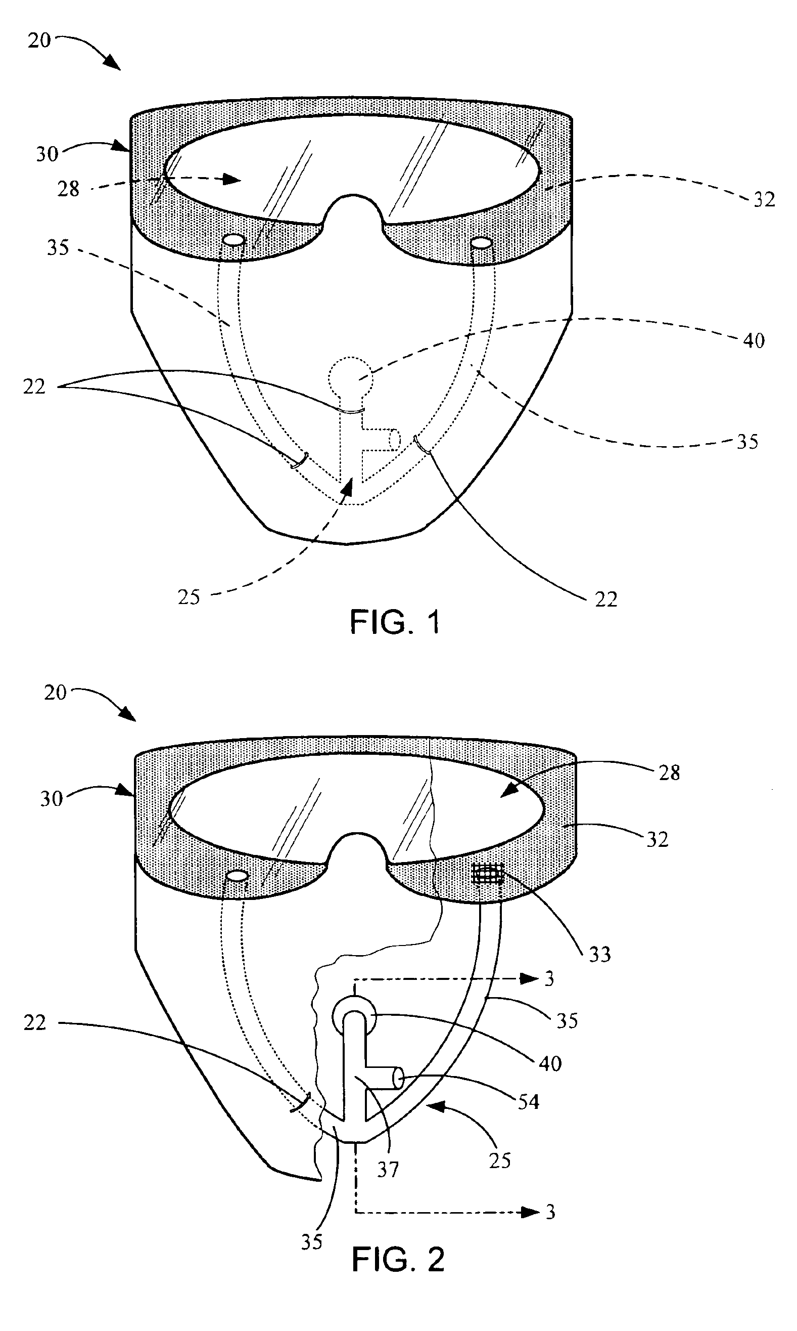
[0019]With reference to the drawings, the new and improved mask defogging system and method according to the present invention will now be described. FIG. 1 shows a face mask 20 having mounting straps 22 supporting a mask defogging system 25 on the inside thereof. The mask defogging system 25 removes fog (moisture or condensate) from an interior mask goggle area 28 on the interior of the mask behind a mask screen or window, such as a window 30.

[0020]Build-up of moisture and humidity in the interior mask goggle area 28 is a common problem with protective ma...


PUM


Abstract

A method for purging air in a goggle area on the interior of a face mask is provided. A mouthpiece is positioned in front of a mouth of a person. Positive purging of air in the goggle area on the interior of the face mask is assured by permitting air to flow from the goggle area on the interior of the face mask to the mouthpiece airway while substantially preventing air flow in the opposite direction to the goggle area. Air is purged through the mouthpiece by affirmative, breath-driven, passive ventilation while permitting a person to breathe freely and without distraction, obstruction, or deliberate action, by normal breathing with the lips in a natural position just behind the mouthpiece. Increased ventilation on the interior of the face mask is selectively forced by puckering the person's lips to engage the mouthpiece while not requiring support or retention of the mouthpiece.

Description

BACKGROUND[0001]1. Technical Field[0002]The present invention relates to ventilation systems for masks, and more particularly to new and improved active / passive ventilation systems and methods for the goggles of a face mask.[0003]2. Background Art[0004]Fog formation on the eye-protecting goggles of face masks has long been a problem. The major difficulty is the limited ventilation in the small space that protects and surrounds the eye area of the wearer. Solutions typically fall into three areas: improving ventilation, heating the transparent screen (window), or coating the screen with water-repellant materials. Some of these solutions have been “passive”, in the sense that they try to prevent fogging of the goggles without requiring external power or affirmative action by the wearer. Some have been “active”, in the sense that they require the wearer to do something to remove or prevent fogging. Some have been “powered”, in the sense that they require external power sources, such as...

Claims


Application Information

Patent Timeline
IPC IPC(8): A61B18/08A61B18/04A62B18/08
CPCA62B18/08
Inventor ZAHRT, JUSTIN W.HOLLOWELL, WILLIAM M.
Owner ZAHRT JUSTIN W
Learn More