Equipment front end module

Active Publication Date: 2022-04-28
PICO & TERA CO LTD
View PDF0 Cites 0 Cited by
  • Summary
  • Abstract
  • Description
  • Claims
  • Application Information

AI Technical Summary

Benefits of technology

[0037]By surrounding the outside of the first chamber with the second chamber in which the pressure therein is maintained at a high pressure, it is possible to effectively prevent external air from flowing into the transfer chamber.
[0038]By surrounding the outside of the transfer chamber with the first chamber in which the pressure therein is maintained at a high pressure, it is possible to effectively prevent harmful gases inside the transfer chamber from escaping out of the EFEM.
[0039]By surrounding the outside of the first chamber with the second chamber in which the pressure therein is maintained at a low pressure, it is possible to effectively prevent external air from flowing into the transfer chamber.
[0040]Through the first and second doors and the first and second communication parts, when the connection of the wafer storage device to the EFEM is released, even in a region where the first

Problems solved by technology

Furthermore, gas inside the transfer chamber may be blocked from escaping out of the EFEM.
Fur

Method used


Image

  • Equipment front end module
  • Equipment front end module
  • Equipment front end module

Examples


first embodiment

[0059]EFEM 10 According to the Present Disclosure

[0060]Hereinafter, an EFEM 10 according to the first embodiment of the present disclosure will be described with reference to FIGS. 1 to 5C.

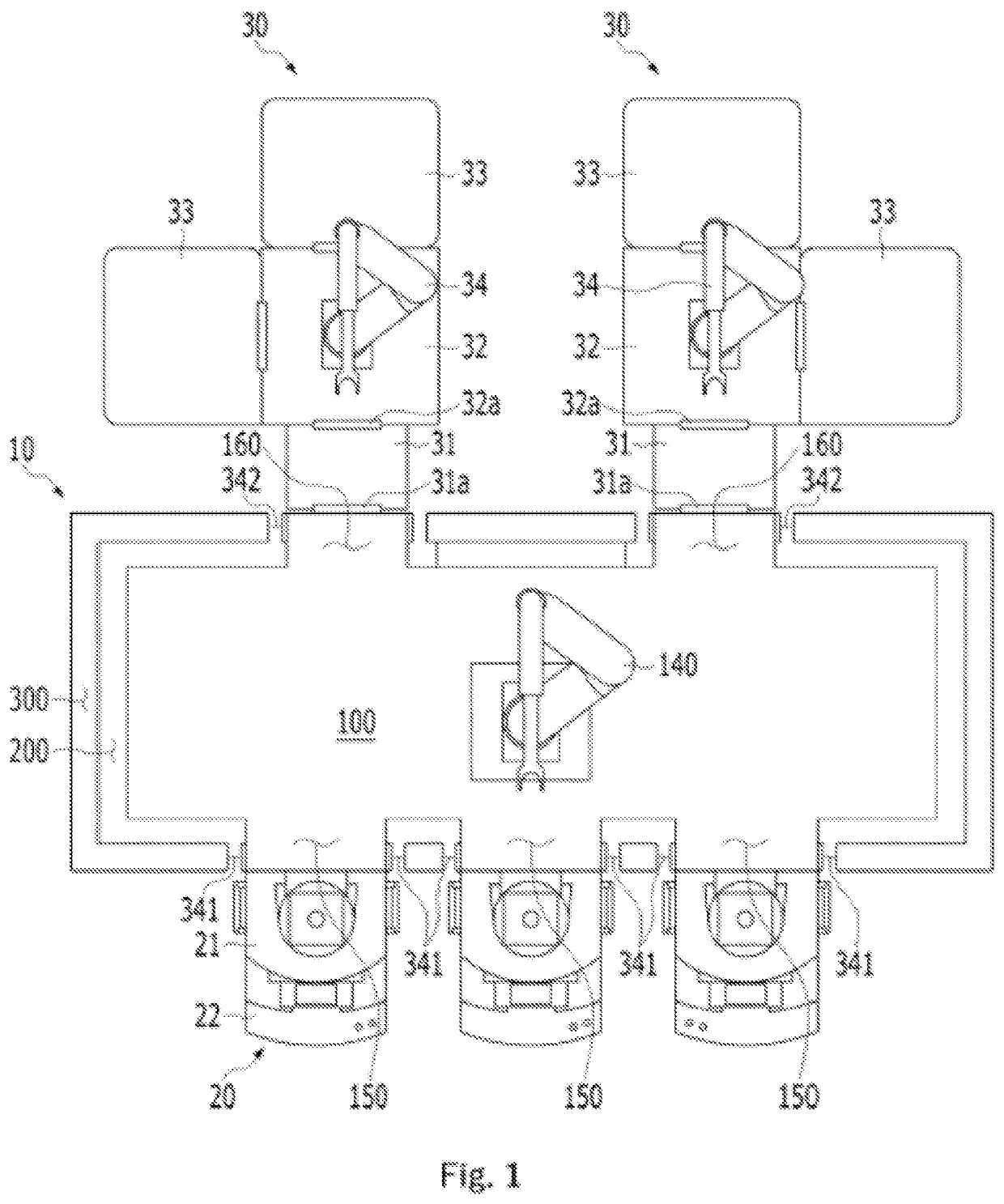
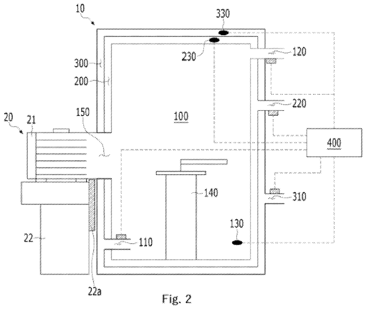
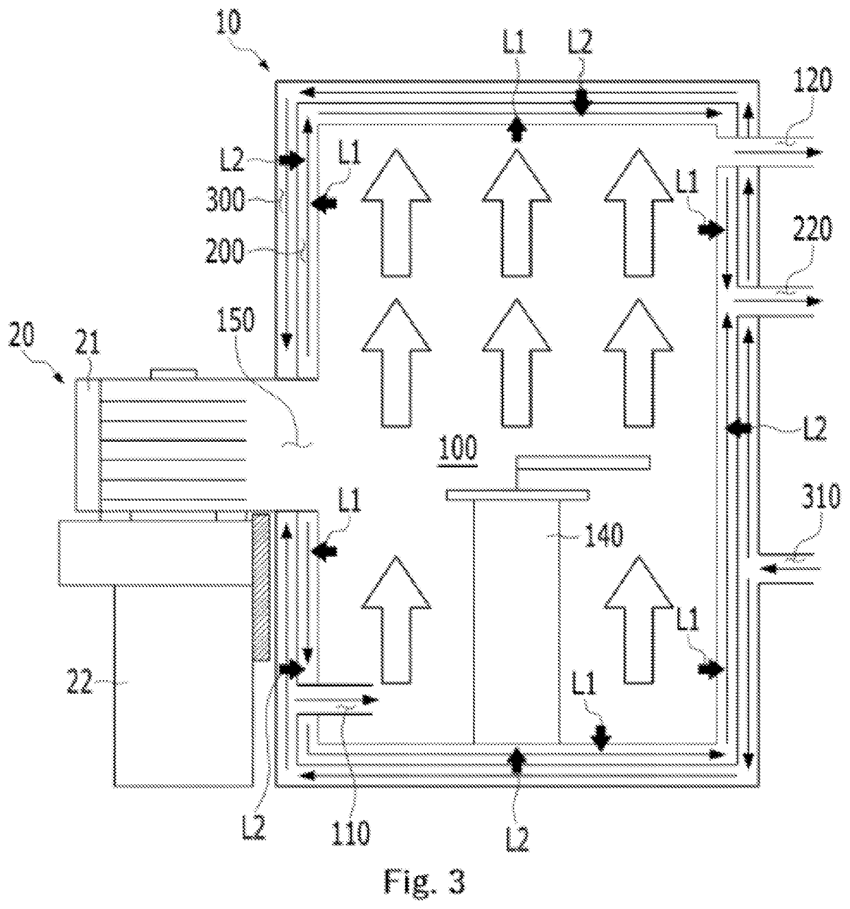
[0061]FIG. 1 is a schematic plan view illustrating that a wafer storage device is connected to a front side of an EFEM according to a first embodiment of the present disclosure, and process equipment is connected to a rear side thereof; FIG. 2 is a side sectional view illustrating the EFEM according to the first embodiment of the present disclosure; FIG. 3 is a side sectional view illustrating the flow of gas in a transfer chamber, a first chamber, and a second chamber of the EFEM according to the first embodiment of the present disclosure; FIG. 4 is a side sectional view illustrating the flow of gas in the transfer chamber, the first chamber, and the second chamber of the EFEM according to the first embodiment of the present disclosure, in which a transfer chamber supply portion and a transfer ch...

second embodiment

[0228]EFEM 10′ According to the Present Disclosure

[0229]Hereinafter, an EFEM 10′ according to the second embodiment of the present disclosure will be described with reference to FIGS. 6 and 7.

[0230]FIG. 6 is a side sectional view illustrating an EFEM according to a second embodiment of the present disclosure, and FIG. 7 is a side sectional view illustrating the flow of gas in a transfer chamber, a first chamber, and a second chamber of the EFEM according to the second embodiment of the present disclosure.

[0231]As illustrated in FIGS. 6 and 7, the EFEM 10′ according to the second embodiment of the present disclosure may include: a transfer chamber 100′ in which wafers are transferred between a wafer storage device 20 and process equipment 30; a first opening 150 for allowing connection of a FOUP 21 of the wafer storage device 20 and the transfer chamber 100′; a second opening 160 for allowing connection of a load lock chamber 31 of the process equipment 30 and the transfer chamber 10...


PUM


Abstract

Proposed is an EFEM configured to perform wafer transfer between a wafer storage device and process equipment. More particularly, proposed is an EFEM that prevents harmful gases inside a transfer chamber in which wafer transfer is performed from escaping out of the EFEM.

Description

CROSS REFERENCE TO RELATED APPLICATION[0001]The present application claims priority to Korean Patent Application No. 10-2020-0138086, filed Oct. 23, 2020, the entire contents of which is incorporated herein for all purposes by this reference.BACKGROUND OF THE INVENTIONField of the Invention[0002]The present disclosure relates to an equipment front end module (EFEM) configured to perform wafer transfer between a wafer storage device and process equipment.Description of the Related Art[0003]In a semiconductor manufacturing process, wafers are processed in a clean room in order to improve yield and quality. However, as devices have become more highly integrated, circuits have become finer, and wafers have become larger, maintaining cleanness in the entire clean room has become difficult from both a technical and cost point of view.[0004]Therefore, in recent years, the cleanliness only in a local space around wafers has been managed. For this purpose, a module called equipment front end...

Claims


Application Information

Patent Timeline
IPC IPC(8): H01L21/673H01L21/677H01L21/67
CPCH01L21/67393H01L21/6773H01L21/67201H01L21/67167H01L21/67386H01L21/67376H01L21/67196H01L21/67772H01L21/67017H01L21/67775H01L21/67126
Inventor WOO, BUM JE
Owner PICO & TERA CO LTD
Why Eureka
Try Eureka