Turbofan

a technology of turbofans and rotors, which is applied in the direction of non-positive displacement fluid engines, radial flow pumps, pump components, etc., can solve the problems of minute gap formed between the fan hub portion and the lower side plate, and the performance of the turbofan deterioration, so as to prevent air flow

Active Publication Date: 2018-12-13
DENSO CORP
View PDF5 Cites 2 Cited by
  • Summary
  • Abstract
  • Description
  • Claims
  • Application Information

AI Technical Summary

Benefits of technology

[0014]assuming a virtual reference gap that corresponds to the fitting gap, in which a length of the reference gap in the axial direction is defined as an axial thickness of the other end side plate in the axial direction, a passage cross-sectional area of the reference gap as a passage through which air passes is constant at any location in the axial direction and equal to a minimum passage cross-sectional area of the fitting gap in the axial direction, and a cross-sectional shape of the reference gap in a cross-section orthogonal to the fan axial center is uniform at any location in the axial direction, then the fitting gap is formed such that an outflow velocity of air on a side opposite from the inter-blade flow path with respect to the other end side plate passes through the fitting gap to outflow to the inter-blade flow path is reduced as compared with an outflow velocity when the air passes through the reference gap to outflow to the inter-blade flow path.
[0015]As described above, the fitting gap is formed such that the outflow velocity when the air on a side opposite from the inter-blade flow path side with respect to the other end side plate passes through the fitting gap to outflow to the inter-blade flow path is reduced as compared with the outflow velocity when the air passes through the reference gap to outflow to the inter-blade flow path. Therefore, a momentum of the air when flowing into the inter-blade flow path from the fitting gap is restricted as compared with a momentum when the air flows into the inter-blade flow path from the reference gap. Therefore, the air flow can be prevented from being separated from the other end side plate (that is, the lower side plate) due to an air inflow from the fitting gap into the inter-blade flow path.

Problems solved by technology

For example, in a turbofan in which the fan hub portion and the lower side plate are molded as separate components, there is a possibility that a minute gap is formed between the fan hub portion and the lower side plate due to a joining play between the fan hub portion and the lower side plate.
The backflow phenomenon causes the air flow to be separated from the surface of the lower side plate in the inter-blade flow path, resulting in a situation in which the performance of the turbofan deteriorates.

Method used


Image

  • Turbofan
  • Turbofan
  • Turbofan

Examples


first embodiment

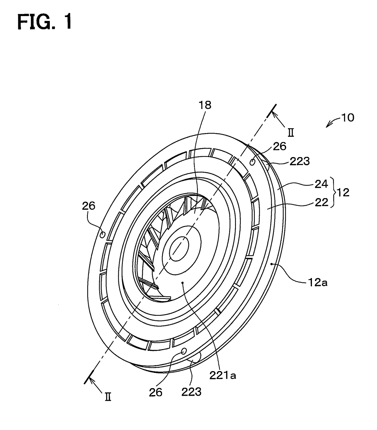
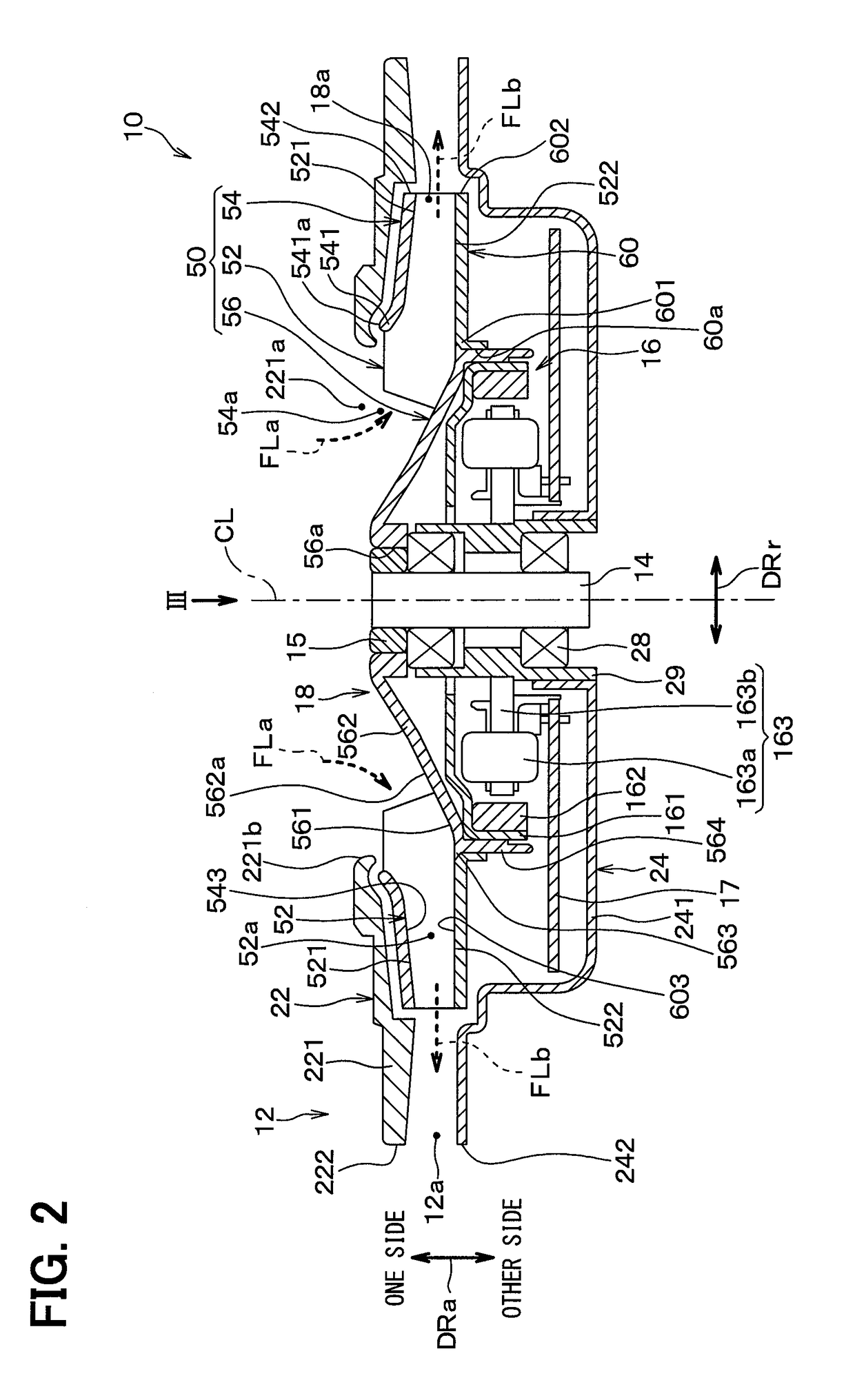
[0034]FIG. 1 is a perspective view illustrating an appearance of a blower 10 in a first embodiment. In addition, FIG. 2 is an axial cross-sectional view of the blower 10 taken along a plane including a fan axial center CL, that is, a cross-sectional view taken along line II-II of FIG. 1. An arrow DRa in FIG. 2 indicates an axial direction DRa of the fan axial center CL, that is, a fan axial center direction DRa. In addition, an arrow DRr in FIG. 2 indicates a radial direction DRr of the fan axial center CL, that is, a fan radial direction DRr.

[0035]As illustrated in FIGS. 1 and 2, the blower 10 is a centrifugal blower, specifically, a turbo type blower. The blower 10 includes a casing 12, a rotating shaft 14, a rotating shaft housing 15, an electric motor 16, an electronic board 17, a turbofan 18, a bearing 28, a bearing housing 29 and the like which are housings of the blower 10.

[0036]The casing 12 protects the electric motor 16, the electronic board 17, and the turbofan 18 from du...

second embodiment

[0118]Next, a second embodiment will be described. In the present embodiment, points different from the above-described first embodiment will mainly be described. In addition, the same or equivalent parts as those in the above-described embodiment will be omitted or simplified. This also applies to a third and subsequent embodiments which will be described later.

[0119]Even in the present embodiment, similar to the first embodiment, the outflow velocity when the side plate external air passes through the fitting gap 604 of the present embodiment and flows out to the inter-blade flow path 52a, is reduced as compared with a case where the air passes through the reference gap 604z of the comparative example illustrated in FIGS. 7 and 8 and flows out to the inter-blade flow path 52a. However, in the present embodiment, the shape of the fitting gap 604 is different from that of the first embodiment.

[0120]Specifically, as illustrated in FIG. 12, an angle al provided by the side plate incli...

third embodiment

[0125]Next, a third embodiment will be described. In the present embodiment, points different from the above-described first embodiment will mainly be described.

[0126]Even in the present embodiment, similar to the first embodiment, the outflow velocity when the side plate external air passes through the fitting gap 604 of the present embodiment and flows out to the inter-blade flow path 52a, is reduced as compared with a case where the air passes through the reference gap 604z of the comparative example illustrated in FIGS. 7 and 8 and flows out to the inter-blade flow path 52a. However, in the present embodiment, the shape of the fitting gap 604 is different from that of the first embodiment.

[0127]Specifically, as illustrated in FIG. 13, the hub inclined surface 565c and the side plate inclined surface 605c are not provided. Therefore, the diameter of the hub fitting surface 565 does not change at any location in the fan axial center direction DRa. In addition, the diameter of the ...


PUM


Abstract

A fan main body member of a turbofan has multiple blades disposed around a fan axial center, a shroud ring coupled to each of the blades, and a fan hub portion coupled to each of the blades on a side opposite from the shroud ring. An other end side plate of the turbofan is joined to each of the other side blade end portions of the blade in a state of being fitted to the radially outer side of the fan hub portion. A fitting gap between the other end side plate and the fan hub portion is formed such that an outflow velocity of air when air passes through the fitting gap and outflows is reduced as compared to when air passes through a virtual reference gap that corresponds to the fitting gap and outflows.

Description

CROSS REFERENCE TO RELATED APPLICATION[0001]This application is based on and claims the benefits of priority of Japanese Patent Application No. 2015-228268 filed on Nov. 23, 2015. The entire disclosure of the application is incorporated herein by reference.TECHNICAL FIELD[0002]The present disclosure relates to a turbofan applied to a blower.BACKGROUND ART[0003]For example, Patent Literature 1 discloses a turbofan included in conventional art. The turbofan disclosed in Patent Literature 1 is a fan for an air conditioner. Specifically, the turbofan of Patent Literature 1 is a closed turbofan in which blades are surrounded by a shroud ring and a main plate among various turbofans.[0004]In the turbofan of Patent Literature 1, among three components including the shroud ring which is a basic configuration of the closed turbofan, multiple blades, and a fan main body including a fan hub portion and a main plate, the fan main body and the blade are integrally molded. In addition, the shroud...

Claims


Application Information

Patent Timeline
Patent Type & Authority Applications(United States)
IPC IPC(8): F04D29/28F04D17/16F04D29/66
CPCF04D29/281F04D17/16F04D29/66F04D25/06F04D29/626F04D29/681
Inventor ISHII, FUMIYAODA, SHUZO
Owner DENSO CORP
Why Eureka
Try Eureka