Air suspension system

a technology of air suspension and bellows, which is applied in the direction of shock absorbers, mechanical equipment, transportation and packaging, etc., can solve the problems of air suspension systems, especially the air suspension bellows, can be damaged, etc., and achieve the effects of preventing air flow, high degree of safety against overpressure, and easy manufacturing

Pending Publication Date: 2022-01-27
SAF HOLLAND GMBH
View PDF3 Cites 0 Cited by
  • Summary
  • Abstract
  • Description
  • Claims
  • Application Information

AI Technical Summary

Benefits of technology

[0019]Preferably the air suspension piston extends along a longitudinal direction, the air suspension bellows being arranged at a first distal end of the air suspension piston in the longitudinal direction, at least one opening having a distance in the longitudinal direction from the first distal end of the air suspension piston, the ratio of the distance to the maximum extension of the air suspension piston in the longitudinal direction being in a range from 0.05 to 0.5, preferably in a range from 0.1 to 0.35 and particularly in a range from 0.2 to 0.3. The longitudinal direction of the air suspension piston can in particular be the direction in which the air suspension piston extends. The longitudinal direction of the air suspension piston is advantageously aligned parallel to this axis of rotational symmetry if the jacket area of the air suspension piston and / or the rolling surface of the air suspension piston is rotationally symmetrical. Alternatively or additionally preferred the longitudinal direction of the air suspension piston is in particular the direction in which the air suspension piston must move for a spring in and spring out movement of the air suspension system. A ratio in the range of 0.05 to 0.5 results in an air suspension system with a particularly wide range of applications. A ratio in the range of 0.1 to 0.35 results in an air suspension system that offers a particularly high degree of safety against overpressure in the internal air volume. A ratio in the range of 0.2 to 0.3 results in an air suspension system that is particularly easy to manufacture.
[0020]Advantageously, the closing body is arranged in such a way that one of its ends, in particular the one facing a connecting area between the air suspension bellows and the air suspension piston, is designed as a free / moving end. In this way a quick closing of the valve arrangement and thus a prevention of air flow through the breakthrough can be achieved in a simple and effective way. Advantageously, the end facing away from the connecting area—between air suspension bellows and air suspension piston—is designed as a film joint in order to be fixed to the air suspension piston in particular.

Problems solved by technology

However, the problem with these air suspension systems known from the state of the art is that if too high a pressure, especially the full boiler pressure, is used when filling the interior of the air suspension system, the air suspension system, especially the air suspension bellows, can be damaged.

Method used


Image

  • Air suspension system
  • Air suspension system
  • Air suspension system

Examples


Embodiment Construction

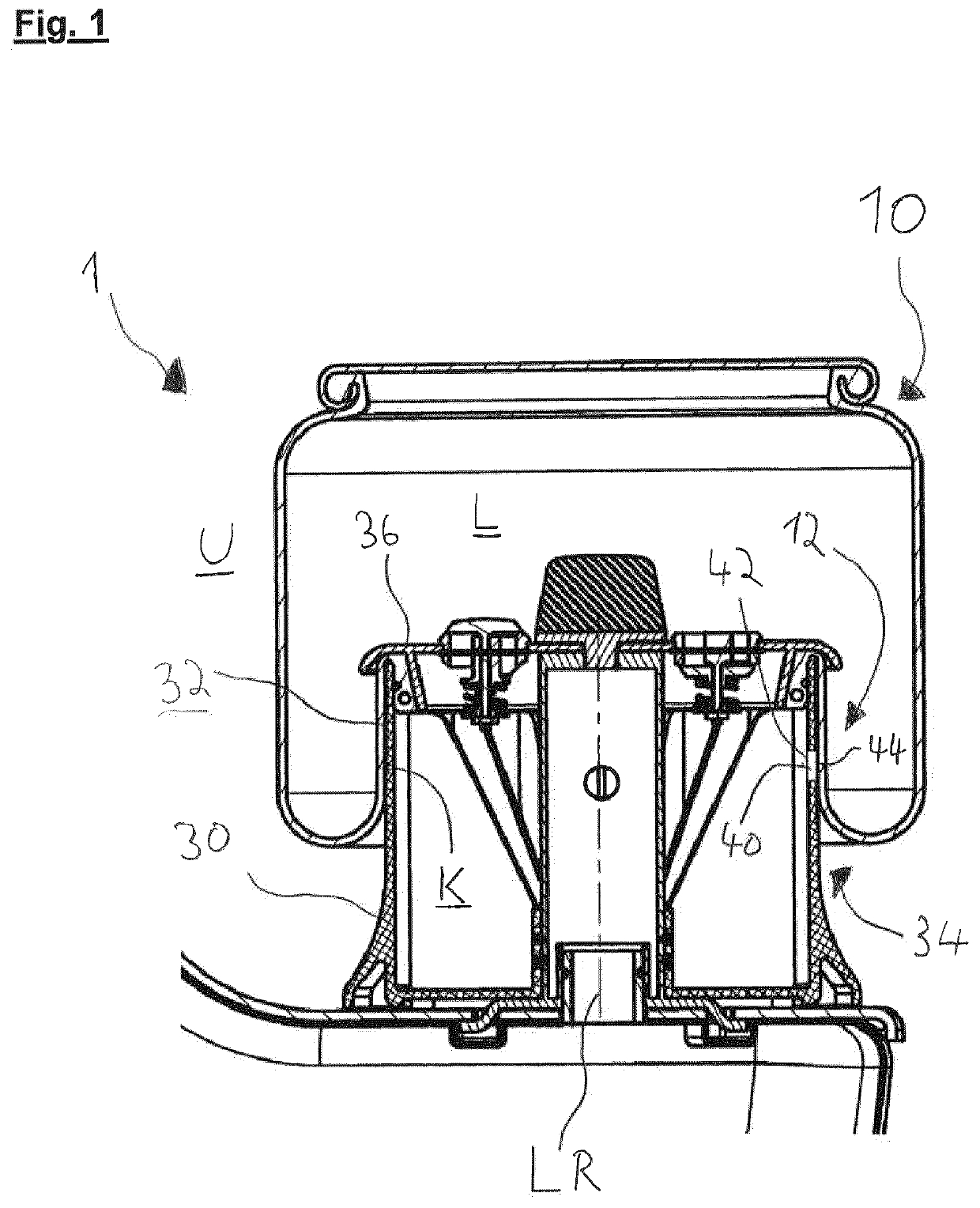
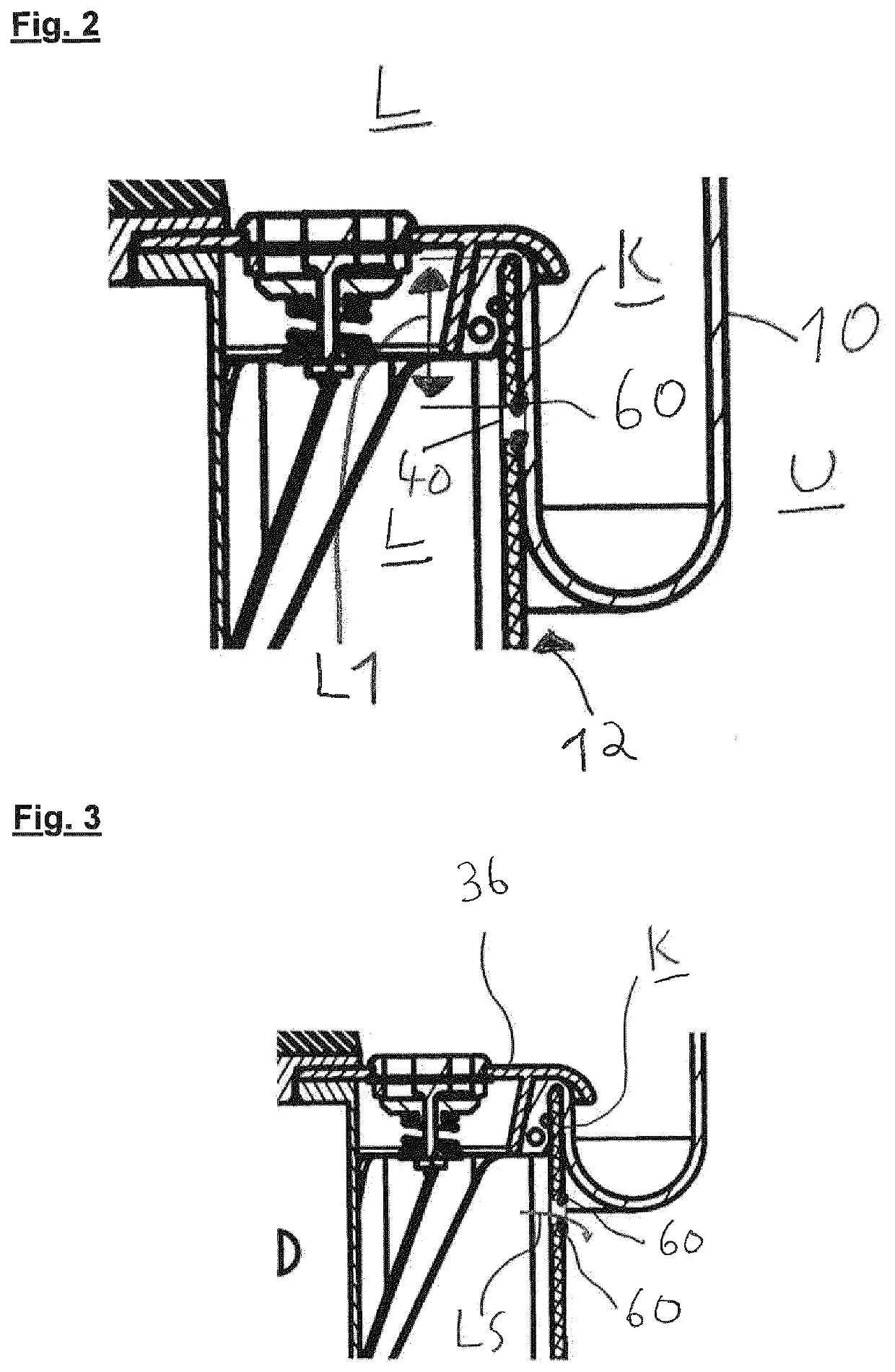
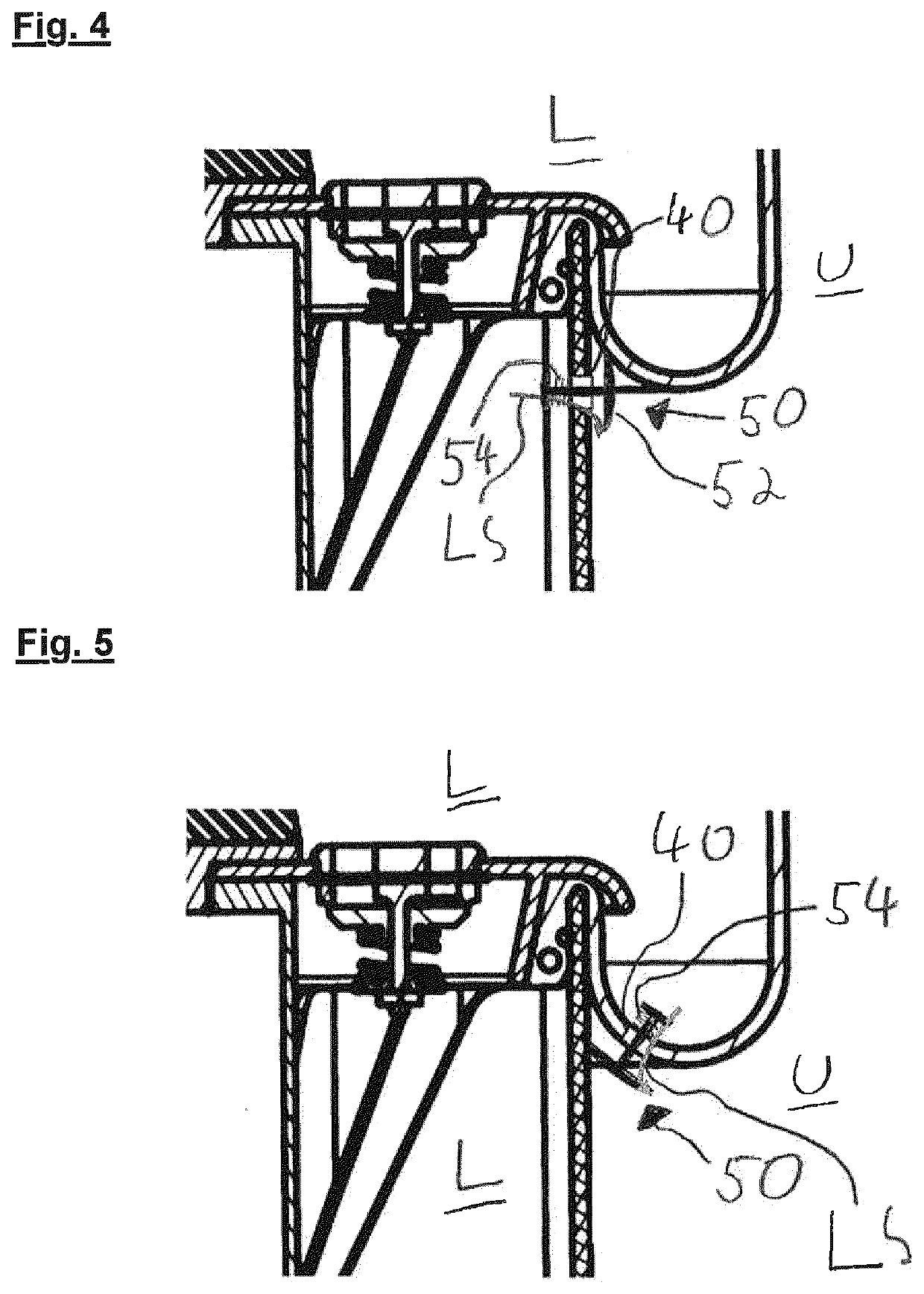
[0029]FIG. 1 shows an air suspension system 1 according to the invention. The air suspension system 1 comprises an air suspension bellows 10 and an air suspension piston 30, which is designed as a plunger in the form shown in FIG. 1. The air suspension bellows 10 has a contact section 12 which is in direct contact with the rolling surface 32 of the air suspension piston 30. These contacting areas of the rolling surface 32 and the contact section 12 define the contact surface K. The air suspension bellows 10 is mechanically connected to the plunger 30 via the clamping plate 36. The plunger 30 has the rolling surface 32 in its jacket area 34. An opening 40 is arranged in the rolling surface 32. This opening 40 has a first end 42 and a second end 44. The first end 42 of the opening 40 opens into the inner air volume L. This inner air volume L is formed by the working volume as well as by the volume inside the air suspension piston 30. These two volumes are fluidically connected to each...


PUM


Abstract

An air suspension system, includes an air suspension bellows connected to a vehicle frame, and an air suspension piston connected to a link, wherein the air suspension bellows and the air suspension piston are connected to each other and enclose an inner air volume, the air suspension piston has a rolling surface for rolling of the air suspension bellows, the air suspension bellows has a contact portion for rolling on the rolling surface, the rolling surface or the contact portion has at least one opening, wherein contacting areas of the rolling surface and the contact portion define a contact surface, and wherein a fluidic connection for an air flow through the at least one opening between the inner air volume and an environment is enabled and prevented by a change in the contact surface that includes a relative movement of the air suspension bellows to the air suspension piston.

Description

BACKGROUND OF THE INVENTION[0001]The invention concerns an air suspension system, in particular for commercial vehicles.[0002]Air suspension systems are already known from the state of the art, these are used to suspend a wheel, axle or shaft from a vehicle frame. For this purpose, an internal air suspension volume is filled with air, whereby this volume can be compressed when the vehicle frame moves relative to the wheel, axle or shaft, so that a cushioning effect is achieved by the air contained in the volume. Such an air suspension system is shown for example in DE 10 2013 110 645 A1, where a valve is switched by the rolling of the air suspension bellows on the plunger in order to achieve a regulation of the spring height. However, the problem with these air suspension systems known from the state of the art is that if too high a pressure, especially the full boiler pressure, is used when filling the interior of the air suspension system, the air suspension system, especially the...

Claims


Application Information

Patent Timeline
Patent Type & Authority Applications(United States)
IPC IPC(8): B60G11/27F16F9/05
CPCB60G11/27F16F9/05F16F2222/126B60G2206/424F16F2230/30B60G2202/152F16F9/057
Inventor BRUNSCH, BERNDDIENER, KONSTANTINBÖNIG, MATTHIAS
Owner SAF HOLLAND GMBH
Why Eureka
Try Eureka