Air control valve

a control valve and air technology, applied in the direction of valve operating means/releasing devices, mechanical energy handling, mechanical apparatus, etc., can solve the problems of motor failure to follow command, increase and/or developing a high contract resistance patina between the brush and the commutator, etc., to achieve the effect of reducing the risk of burning the commutator and/or reducing the risk of commutator burnou

Active Publication Date: 2021-03-11
GM GLOBAL TECH OPERATIONS LLC
View PDF0 Cites 0 Cited by
  • Summary
  • Abstract
  • Description
  • Claims
  • Application Information

AI Technical Summary

Benefits of technology

[0005]According to several aspects of the present disclosure, an automotive air control valve comprises a housing, the housing defining an air flow path, a blade pivotally mounted within the housing, the blade pivotable between a closed position, wherein the blade substantially blocks air flow through the housing, and an open position, wherein air can flow through the housing, an actuator adapted to selectively pivot the blade between the open and closed positions, and an over-center cam mechanism, wherein the over-center cam mechanism is adapted to bias the blade in the open position when the blade has been pivoted to the open position, and to bias the blade in the closed position when the blade has been pivoted to the closed position.

Problems solved by technology

Holding a brushed electric motor actuator in a fixed position increases the risk of burning the commutator and / or developing high contract resistance patina between the brush and commutator.
These conditions lead to the motor failing to follow command.
Both options consume greater electrical power.
Furthermore, when using an electric motor, the electric motor will heat up.
Holding an electric motor in a fixed position for extended periods results in heating up of the copper coils within the DC motor.
Larger motors run slower and add both weight and cost to the automobile.

Method used


Image

  • Air control valve
  • Air control valve
  • Air control valve

Examples


Embodiment Construction

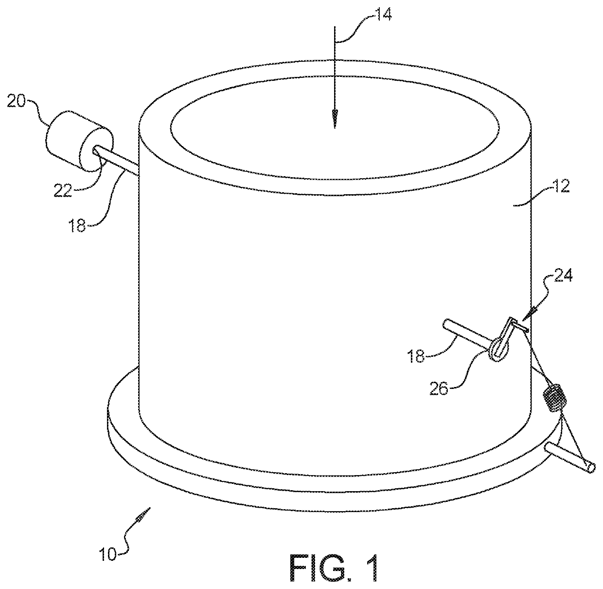
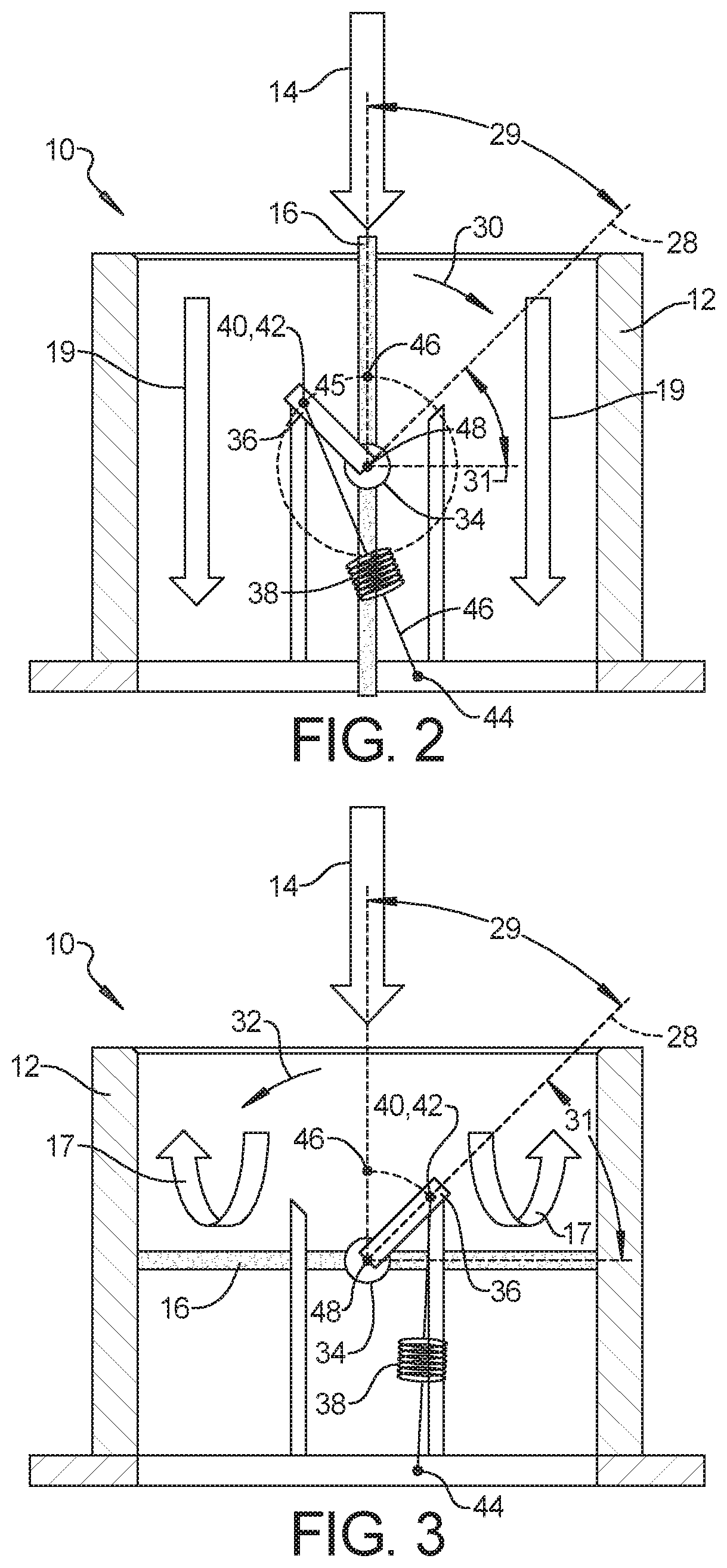
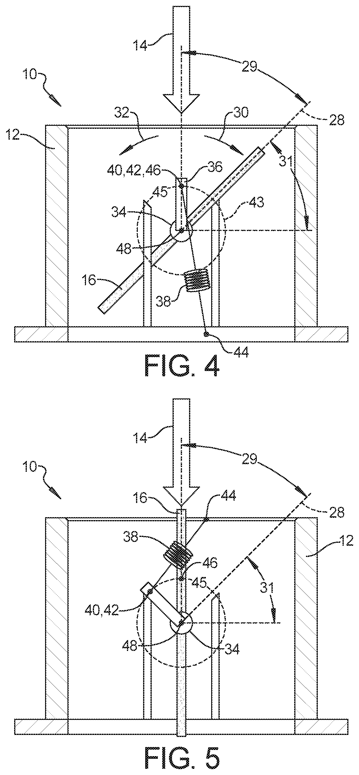
[0040]The following description is merely exemplary in nature and is not intended to limit the present disclosure, application, or uses. Referring to FIG. 1, FIG. 2, and FIG. 3, an automotive air flow valve 10 in accordance with the present disclosure is generally shown. The air control valve 10 is adapted to control the flow of air within a fuel cell, within an exhaust gas recovery by-pass unit, or for air intake / exhaust from an internal combustion engine within and automobile. The automotive air control valve 10, comprises a housing 12 that defines an air flow path 14 extending therethrough. A blade 16 is pivotally mounted within the housing 12. The blade 16 is pivotable between a closed position, as shown in FIG. 3, wherein the blade 16 substantially blocks air flow through the housing 12, as indicated by arrows 17 and an open position, as shown in FIG. 2, wherein air can flow through the housing 12, as indicated by arrows 19. In an exemplary embodiment, the blade 16 is supported...


PUM


Abstract

An automotive air control valve comprises a housing, the housing defining an air flow path, a blade pivotally mounted within the housing, the blade pivotable between a closed position, wherein the blade substantially blocks air flow through the housing, and an open position, wherein air can flow through the housing, an actuator adapted to selectively pivot the blade between the open and closed positions, a first stop that provides a positive stop for the blade when rotated to the open position, a second stop that provides a positive stop for the blade when rotated to the closed position; and an over-center cam mechanism, wherein the over-center cam mechanism is adapted to bias the blade in the open position when the blade has been pivoted to the open position, and to bias the blade in the closed position when the blade has been pivoted to the closed position.

Description

INTRODUCTION[0001]The present disclosure relates to an air control valve for use in an automobile. Air flow valves, particularly those used in fuel cell systems, exhaust gas recovery systems, and air intake / exhaust systems within automobiles are often biases to a default position. This means that if the valve fails, or if power to the valve is cut off, the valve defaults to a position. These valves generally include a spring bias to move the valve to the default position and use an electric actuator or motor to selectively actuate the valve away from the default position.[0002]For instance, if the valve defaults to closed, the valve only opens when the electric actuator is powered and moves the valve against the spring bias to open the valve. With this set up, the valve will only remain open when the electric actuator is powered. This means that power will need to continue to the actuator for as long as it is necessary to have the valve open. Holding a brushed electric motor actuato...

Claims


Application Information

Patent Timeline
Patent Type & Authority Applications(United States)
IPC IPC(8): F16K31/52H02K5/20F16K31/524
CPCF16K31/521F16K31/524H02K5/20H02K7/14H02K2213/03F16K3/04F16K31/563
Inventor SORRELL, DEAN G.STOCKBRIDGE, JOHN NORMAN
Owner GM GLOBAL TECH OPERATIONS LLC
Why Eureka
Try Eureka