Constant velocity turbine and stator assemblies

a constant velocity turbine and stator technology, applied in the direction of functional valve types, transportation and packaging, lighting and heating apparatus, etc., can solve the problems of adversely affecting the desired water distribution, and achieve the effect of effective and efficient compensation for variable fluid flow rate and pressure, constant rotation rate of the nozzle, and preventing excessive wear of the rotating parts

Inactive Publication Date: 2005-07-26
TORO CO THE
View PDF11 Cites 32 Cited by
  • Summary
  • Abstract
  • Description
  • Claims
  • Application Information

AI Technical Summary

Benefits of technology

[0012]It is a further object of the present invention to provide a rotary sprinkler system having a consistent and predictable watering pattern and volume.
[0013]It is a further object of the present invention to provide a rotary sprinkler system that effectively and efficiently compensates for variable fluid flow rates and pressures.
[0014]It is a further object of the present invention to provide a rotary sprinkler system that prevents excessive wear on the rotating parts of the system.
[0015]It is a further object of the present invention to provide a rotary sprinkler system that controls the rate of rotation of the nozzle.
[0016]It is a further object of the present invention to provide a rotary sprinkler system that maintains a constant rate of rotation of the nozzle.

Problems solved by technology

In general, increases or decreases in nozzle speed can adversely affect the desired water distribution.

Method used


Image

  • Constant velocity turbine and stator assemblies
  • Constant velocity turbine and stator assemblies
  • Constant velocity turbine and stator assemblies

Examples


Embodiment Construction

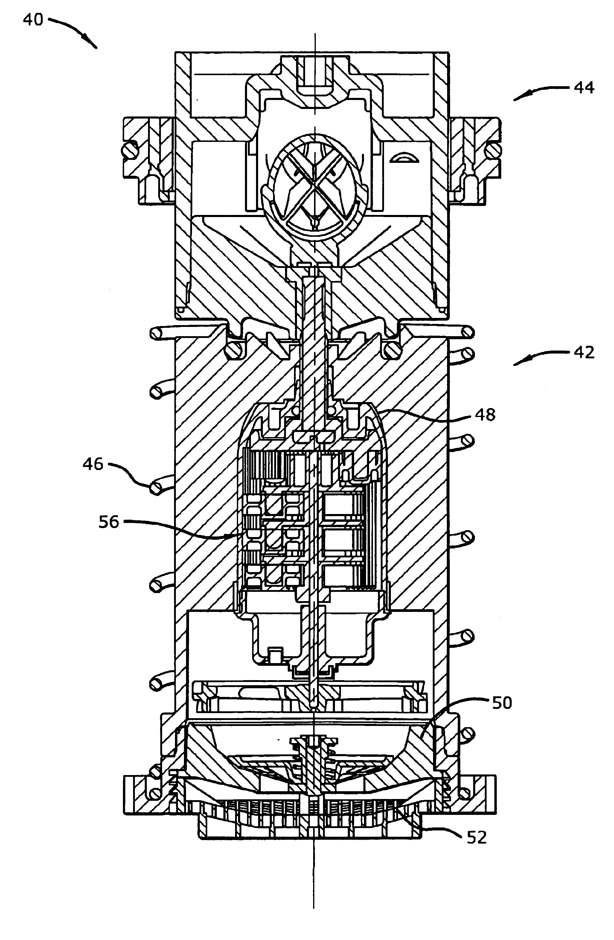
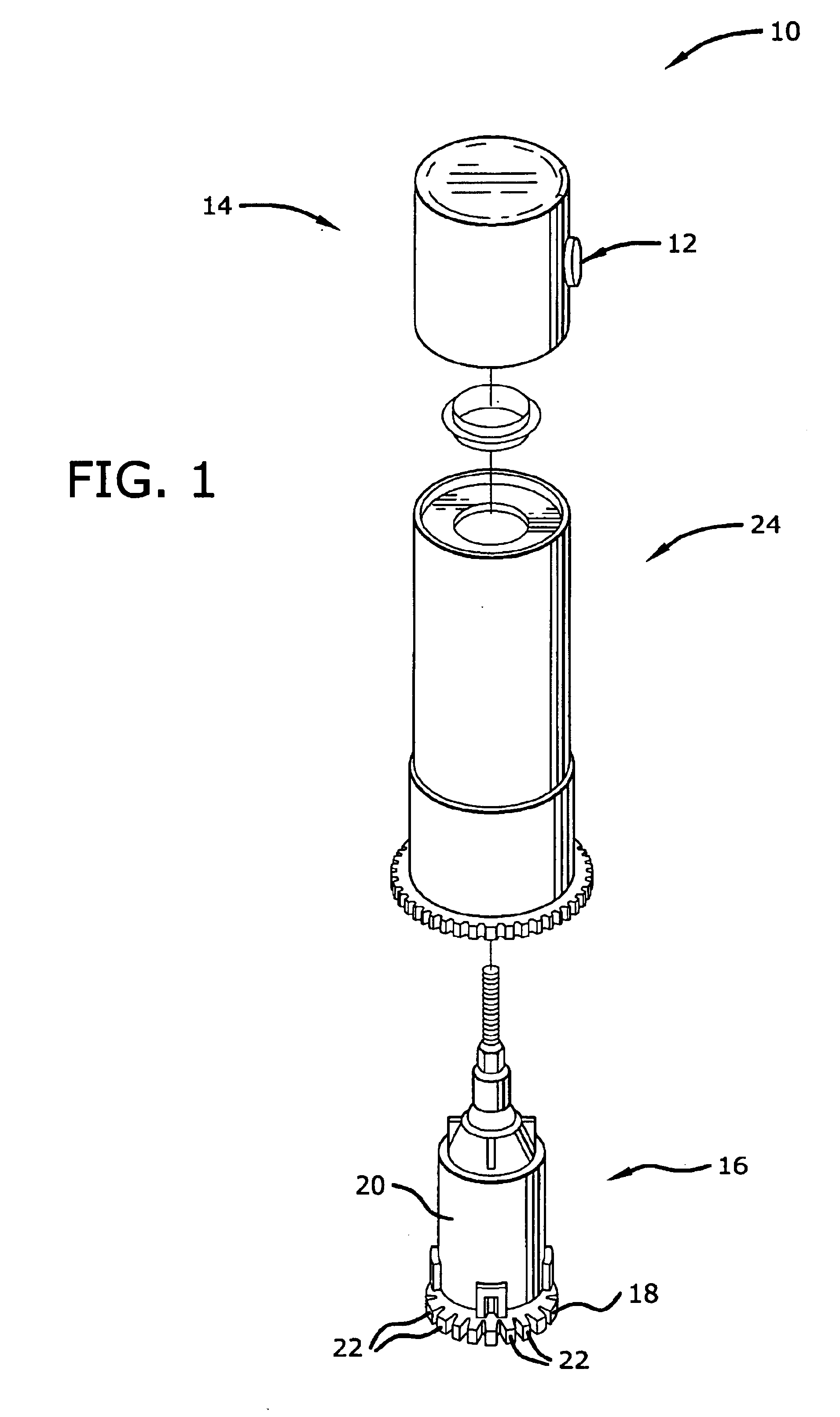
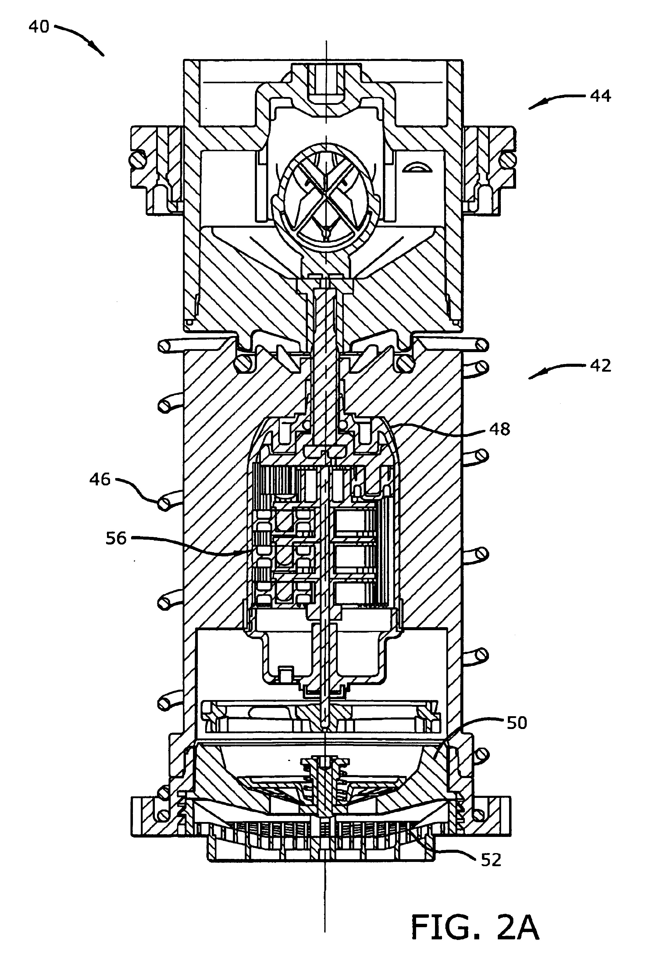
[0038]Referring to FIGS. 2A and 2B, an embodiment of a rotary sprinkler system 40 in accordance with the present invention includes a riser assembly 42 and a nozzle base assembly 44 which are housed within a generally cylindrical housing (not shown). A return spring 46, also housed within the cylindrical housing, surrounds a portion of the riser assembly 42. The return spring 46 is compressible by water pressure and configured to cause the riser assembly 42, and hence the nozzle base assembly 44, to pop up out of the housing during use of the rotary sprinkler system. Although the following description is made with reference to pop-up type sprinklers, the invention is not limited thereto and can be used with any conventional rotating type sprinkler head.

[0039]Housed within the riser assembly 42 are a drive assembly 48, a stator assembly 50 and a screen 52. The screen 52, which is located near the fluid in-flow end of the sprinkler, prevents or greatly reduces the amount of debris, sa...


PUM


Abstract

A rotary sprinkler system for both above-the ground and pop-up rotary sprinkler systems that controls the rate of nozzle rotation is disclosed. To maintain a relatively constant and controlled nozzle rotation, one or more chamfered spokes are included on the turbine of the sprinkler system. This turbine configuration together with a stator assembly that regulates fluid flow to the turbine control nozzle rotation despite variations in fluid flow. In particular, the chamfered spokes counteract the spin of the turbine in direct relation to the amount of water that bypasses the driving blades of the turbine.

Description

CROSS REFERENCE TO RELATED APPLICATIONS[0001]The present application claims priority to U.S. Provisional Patent Application No. 60 / 357,220, filed Feb. 14, 2002, whose contents are fully incorporated herein by reference.BACKGROUND OF THE INVENTION[0002]Sprinkler systems for turf irrigation are well known. Typical systems include a plurality of valves and sprinkler heads in fluid communication with a water source, and a centralized controller connected to the water valves. At appropriate times the controller opens the normally closed valves to allow water to flow from the water source to the sprinkler heads. Water then issues from the sprinkler heads in predetermined fashion.[0003]There are many different types of sprinkler heads, including above-the-ground heads and “pop-up” heads. Pop-up sprinklers, though generally more complicated and expensive than other types of sprinklers, are thought to be superior. There are several reasons for this. For example, a pop-up sprinkler's nozzle o...

Claims


Application Information

Patent Timeline
Patent Type & Authority Patents(United States)
IPC IPC(8): B05B3/04B05B3/02B05B15/00B05B15/10B05B3/00
CPCB05B3/003B05B3/0422B05B15/10B05B15/74Y10T137/269Y10T137/7837
Inventor RENQUIST, STEVEN C.
Owner TORO CO THE
Why Eureka
Try Eureka