
Numerically controlled method

a numerical control and method technology, applied in the direction of program control, electric programme control, instruments, etc., can solve the problems of reducing affecting the accuracy of the control method, and introducing an element of delay into the control method, so as to achieve the effect of reducing the irregularity or position shift of the feeding process and high accuracy

Inactive Publication Date: 2005-07-26
YAMAZAKI MAZAK KK
View PDF16 Cites 15 Cited by
  • Summary
  • Abstract
  • Description
  • Claims
  • Application Information

AI Technical Summary

Benefits of technology

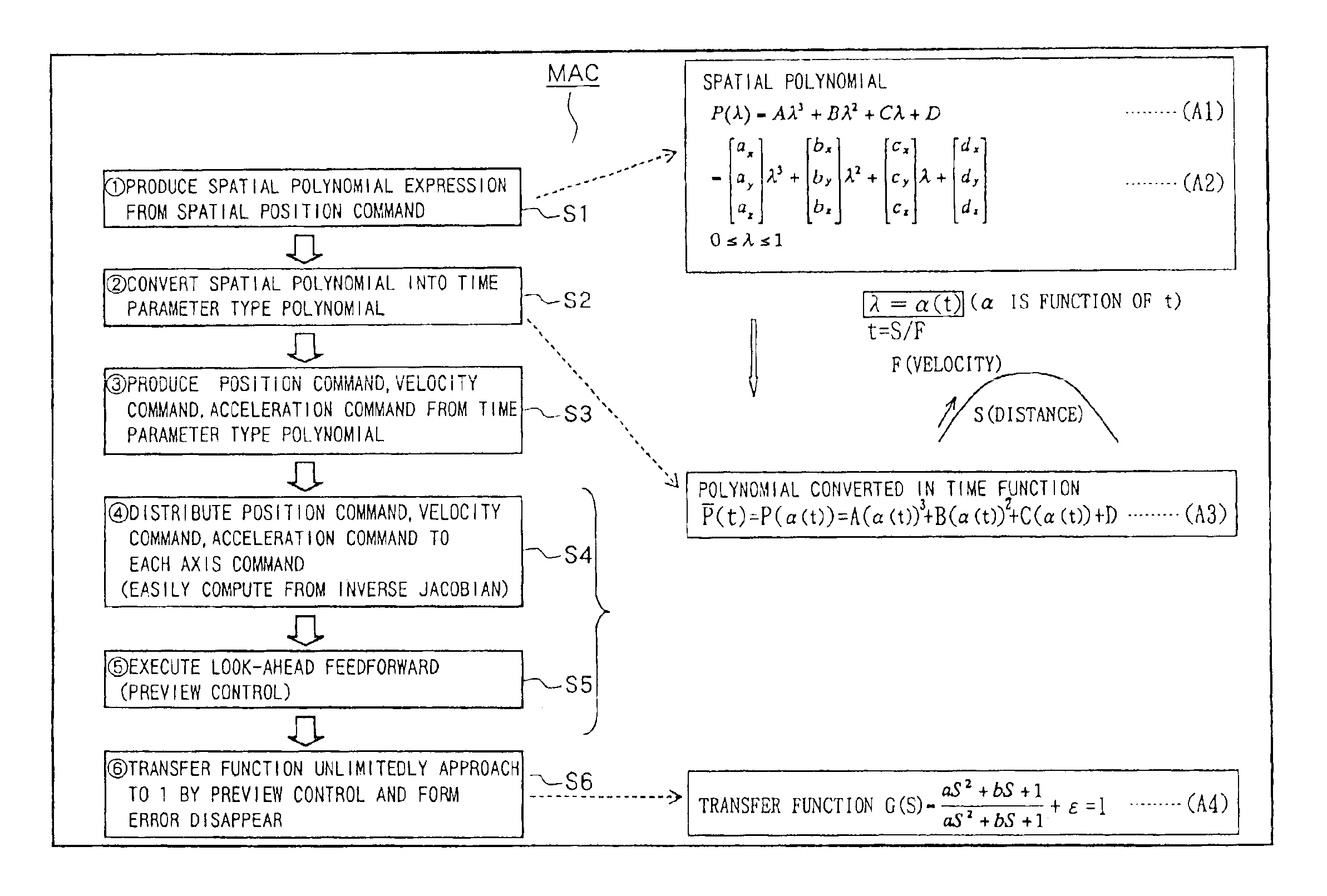
[0011]The velocity, the acceleration, the jerk of a top end of a torch (or a top end of a tool) can be easily obtained for each control axis without time delay by deriving the polynomial which has been converted into time function. Each control axis is driven and controlled on the basis of the control parameter, such as the velocity and the acceleration obtained in this way. Therefore, the preview control wherein future moving state of an object to be controlled is foresaw and control is executed so as to correspond with the foreseeing is possible. By doing so, it is possible to provide a numerically controlled method wherein the motion of the object to be controlled is correctly controlled along the locus expressed by the polynomial, feeding irregularity or position shift is reduced, and machining on curved face or the like can be executed at high accuracy.

Problems solved by technology

The difficulty in using such a method of determining velocity and acceleration through the use of feedback monitoring is that it introduces an element of delay into the control method, since, by the time the control parameter is computed, the machine has passed beyond the discrete point which the analysis is intended to model.
As a result, when machining is executed at high speed, or when the tool is forced to negotiate a particularly severe curved section of a workpiece, substantial errors can result from this delay.
Thus, the machining operation can be difficult to properly control and machining tolerance errors can result.
Therefore, the movement of the working point of the tool, which is the composite movement of each axis, is not smooth and will include irregularities.
Besides, when a nonlinear element is encountered, it is necessary to limit the system to prevent sudden changes in velocity and acceleration that are beyond the limits of the tool, or which will introduce unacceptable machining error into the workpiece.
With the conventional method, in which the velocity command and the acceleration command are produced from the position command which itself is based on a sample taken at a particular sampling time, then adequate control may be impossible.
This results in an increase in error between the actual position of the tool and the commanded position of the tool.

Method used


Image

  • Numerically controlled method
  • Numerically controlled method
  • Numerically controlled method

Examples


Embodiment Construction

[0033]Embodiments of the present invention will now be explained hereinafter, referring to drawings.

[0034]FIG. 3 shows a laser beam machine of the present embodiment. The laser beam machine 1 can have a base 2, with a table 3 provided on the base 2 being free to move and be driven in a horizontal X axis direction, as shown in FIG. 3. On the table 3, a workpiece W can be positioned for machining. A column 5 is provided on the base 2, bridging over the table 3, and having a saddle 6 that is free to move and be driven in a horizontal Y axis direction (the direction orthogonal to the X axis direction).

[0035]The saddle 6 has a head unit 7, which is free to move and be driven along the Z axis. Referring to FIG. 3(b), the head unit 7 is comprised of a first portion 7a on the saddle 6 side, a second portion 7b, being free to rotate and be driven along an axis “A” with respect to the first portion 7a, and having an axial center CT1 of the first portion 7a parallel to the Z-axis. A third port...


PUM


Abstract

In a numerically controlled method of moving an object to be controlled along a predetermined locus, controlling control axes, the locus is made approximate to a spatial polynomial, a polynomial is converted into a polynomial as time function, the polynomial converted as time function is distributed to each control axis, control command in each control axis is produced on the basis of the polynomial distributed to each axis as time function, and the object to be controlled is moved along the locus, controlling each control axis on the basis of the control command. The velocity, the acceleration and the jerk of the object to be controlled can be easily obtained concerning each control axis in advance by differentiating the polynomial expressed by time function. The object to be controlled is controlled so as to move along the locus expressed by the polynomial, feeding irregularity or position shift is reduced and curved face machining at high accuracy is possible.

Description

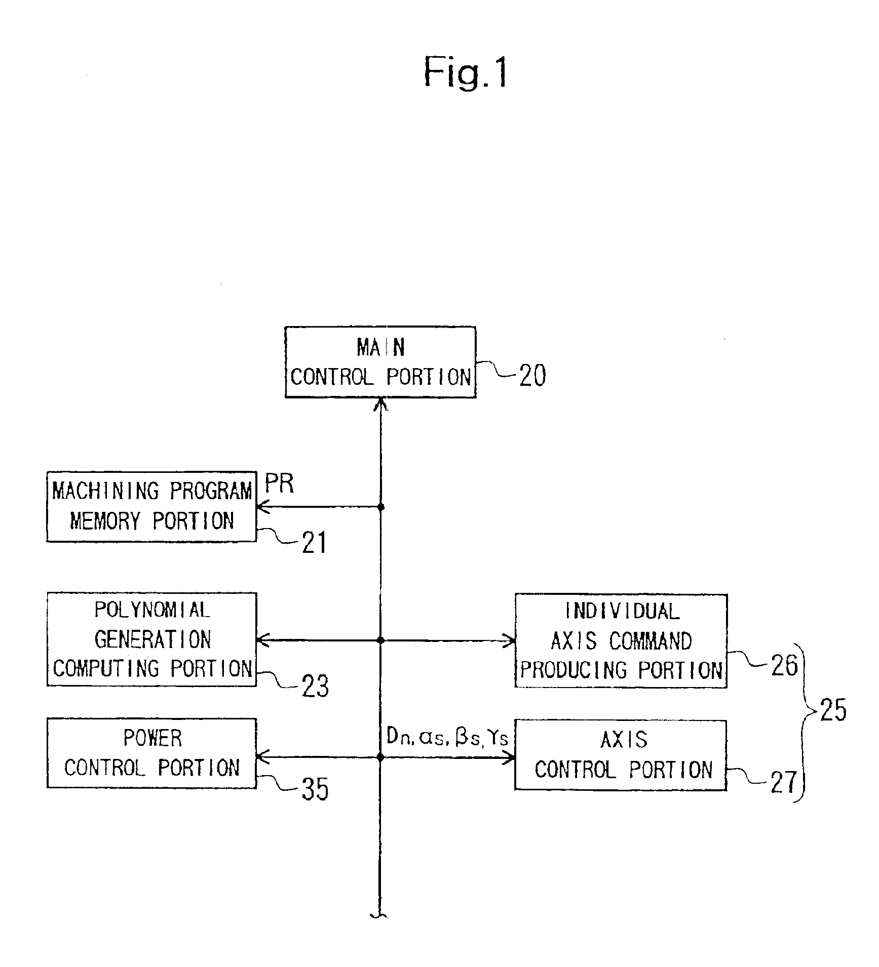
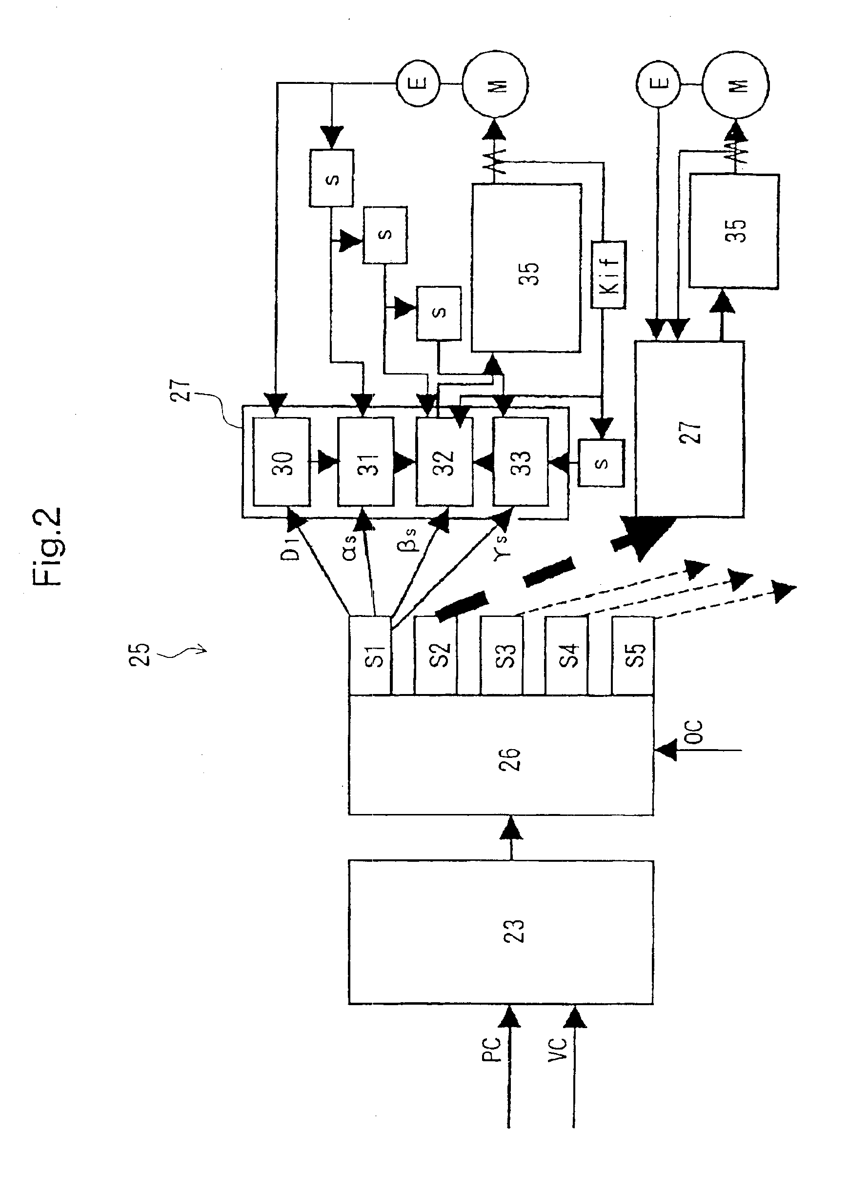
CROSS REFERENCE TO RELATED APPLICATION[0001]This is a continuation-in-part of co-pending U.S. non-provisional application Ser. No. 10 / 004,640, filed Dec. 5, 2001, which claims priority to Japanese national patent application serial 2000-371386, filed Dec. 6, 2000; the entirety of which applications are incorporated herein by reference.FIELD OF INVENTION[0002]This invention relates to a numerically controlled method capable of machining on curved face and the like at high accuracy.BACKGROUND OF THE INVENTION[0003]FIG. 7 shows a conventional servo control system. When servo control of each axis is performed using a three dimensional spatial position command, a conventional servo control system 60 (such as one used for a laser beam machine and a machining center) instructs an axis command producing portion 50 to produce a motion command for each control axis necessary to effect a spatial position command and velocity command instructed by a machining program.[0004]The motion command fo...

Claims


Application Information

Patent Timeline
Patent Type & Authority Patents(United States)
IPC IPC(8): G05B19/408
CPCG05B19/4086G05B2219/34089G05B2219/37323G05B2219/41436
Inventor YAMAZAKI, TSUNEHIKOOHNISHI, KOHEIMIYAGAWA, NAOOMIINOUE, TOSHIHIKO
Owner YAMAZAKI MAZAK KK
Learn More