Shifting device for manufacturing continuous terminals

a technology of shifting device and manufacturing terminal, which is applied in the direction of manufacturing tools, contact member manufacturing, metal working apparatus, etc., can solve the problems of increasing material costs, difficult implementation of manufacturing processes, and inability to optimize materials in this terminal arrangement, so as to simplify the process of manufacturing terminals without waste material and the pressing and crimping process.

Inactive Publication Date: 2005-08-02
TSAI CHOU HSUAN
View PDF1 Cites 1 Cited by
  • Summary
  • Abstract
  • Description
  • Claims
  • Application Information

AI Technical Summary

Benefits of technology

[0010]It is therefore an object of the invention to provide a shifting device for shifting continuous terminals by a suitable distance after the continuous terminals travel a distance. Thus, one row of opposite continuous terminals can be shifted away from the other row of opposite continuous terminals. In addition, the two rows of continuous terminals after being shifted travel in parallel. Thus, the pressing and crimping processes can be simplified.
[0011]To achieve the above-mentioned objects, a shifting device for shifting continuous terminals includes a body and a shaft. The continuous terminals include a first row of continuous terminals and a second row of continuous terminals opposite to the first row of continuous terminals. The body is formed with a hole and an inlet and an outlet both communicating with the hole. A direction into the inlet and a direction out of the outlet are the same. The inlet is shifted a predetermined distance away from the outlet. The shaft is fitted with the hole of the body and defines a spiral channel with the body after fitting with the hole of the body. The spiral channel corresponds to the inlet and the outlet of the body. The second row of continuous terminals enters the spiral channel from the inlet and goes out of the spiral channel from the outlet while the first row of continuous terminals travels over the inlet such that the second row of continuous terminals is shifted the predetermined distance away from the first row of continuous terminals at the outlet. According to the structure, the second row of continuous terminals enters the body from the inlet and travels along the spiral channel. Then, the second row of continuous terminals travels out of the body from the outlet with a predetermined distance shifted away from the first row of continuous terminals. Thus, the processes for manufacturing terminals without waste material can be simplified.

Problems solved by technology

In the above-mentioned manufacturing processes, although it is convenient to form two rows of continuous terminals at one time, the material can not be optimized in this terminal arrangement.
That is, because regions 17 between any two adjacent terminals are the non-used parts, a lot of waste material during the pressing processes may be formed, thereby increasing the material costs.
There are so many disadvantages in the above-mentioned manufacturing processes that the manufacturing processes are difficulty to be implemented.
Therefore, the costs of the press die may be relatively high.

Method used


Image

  • Shifting device for manufacturing continuous terminals
  • Shifting device for manufacturing continuous terminals
  • Shifting device for manufacturing continuous terminals

Examples


Embodiment Construction

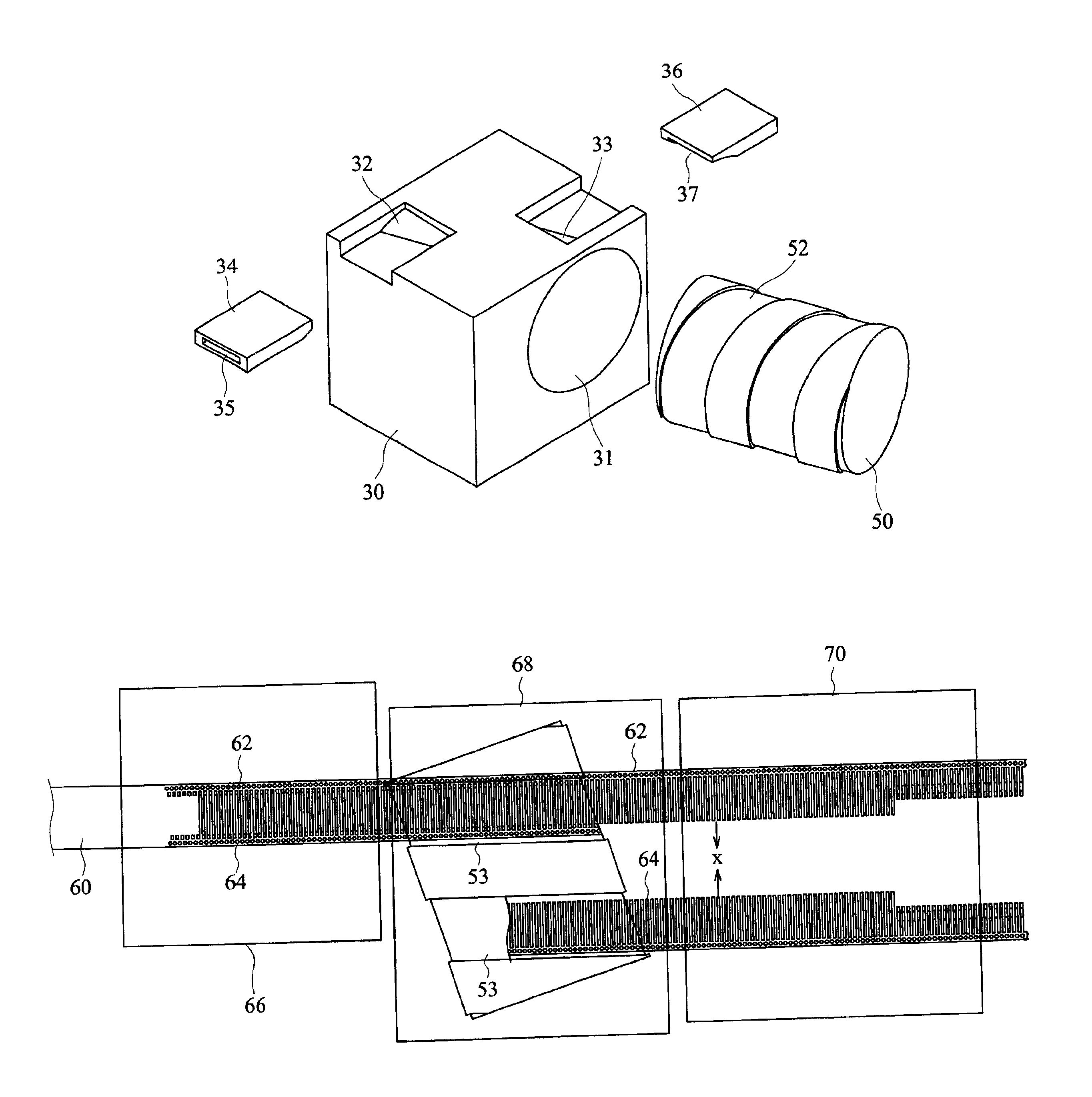
[0021]Referring to FIGS. 4 to 6, the shifting device for shifting continuous terminals in accordance with a preferred embodiment of the invention includes a body 30, two conduits 34 and 36, and a shaft 50. The continuous terminals include a first row of continuous terminals 62 and a second row of continuous terminals 64 opposite to the first row of continuous terminals 62, as shown in FIG. 7.

[0022]The body 30 is formed with a hole 31 and an inlet 32 and an outlet 33 both communicating with the hole 31. The direction into the inlet 32 and the direction out of the outlet 33 are the same. The inlet 32 is shifted a distance away from the outlet 33.

[0023]The two conduits 34 and 36, through which the second row of continuous terminals 64 passes, are horizontally placed on the inlet 32 and outlet 33 of the body 30. The conduit 34 is formed with an inner passageway 35 communicating with the hole 31 via the inlet 32. The conduit 36 is formed with an inner passageway 37 communicating with the...


PUM

PropertyMeasurementUnit
distanceaaaaaaaaaa
thicknessaaaaaaaaaa
timeaaaaaaaaaa

Abstract

A shifting device for shifting two rows of continuous terminals includes a body and a shaft. The body is formed with a hole and an inlet and an outlet both communicating with the hole. A direction into the inlet and a direction out of the outlet are the same. The inlet is shifted a predetermined distance away from the outlet. The shaft is fitted with the hole of the body and defines a spiral channel with the body after fitting with the hole of the body. The spiral channel corresponds to the inlet and the outlet of the body According to the structure, one row of the continuous terminals enters the body from the inlet and travels along the spiral channel and travels out of the body from the outlet with a predetermined distance shifted away from the other row of the continuous terminals.

Description

BACKGROUND OF THE INVENTION[0001]1. Field of the Invention[0002]The invention relates to a shifting device, in particular to a shifting device for shifting continuous terminals.[0003]2. Description of the Related Art[0004]FIG. 1 is a schematic illustration showing a conventional process for pressing continuous terminals. As shown in FIG. 1, two rows of continuous terminals 12 and 14 are formed by pressing a continuous copper band 10 using a press die. Then, the two rows of continuous terminals 12 and 14 are cut along a separation region 16. Thus, it is convenient to form two rows of continuous terminals at one time.[0005]In the above-mentioned manufacturing processes, although it is convenient to form two rows of continuous terminals at one time, the material can not be optimized in this terminal arrangement. That is, because regions 17 between any two adjacent terminals are the non-used parts, a lot of waste material during the pressing processes may be formed, thereby increasing t...

Claims


Application Information

Patent Timeline
Patent Type & Authority Patents(United States)
IPC IPC(8): H01R43/16
CPCH01R43/16Y10T29/53213Y10T29/5193Y10T29/53235Y10T29/49204Y10T29/53261Y10T29/49121Y10T29/49117Y10T29/49222Y10T29/532Y10T29/53209
Inventor TSAI, CHOU HSUAN
Owner TSAI CHOU HSUAN
Why Eureka
Try Eureka