Top side reference cavity for absolute pressure sensor
What is Al technical title?
Al technical title is built by PatSnap Al team. It summarizes the technical point description of the patent document.
a technology of absolute pressure sensor and reference cavity, which is applied in the field of absolute pressure sensor, can solve the problems of typical pressure sensor failure and common failure of pressure sensor
Active Publication Date: 2005-08-02
HONEYWELL INT INC
View PDF9 Cites 94 Cited by
Summary
Abstract
Description
Claims
Application Information
AI Technical Summary
This helps you quickly interpret patents by identifying the three key elements:
Problems solved by technology
Method used
Benefits of technology
[0005]It is a feature of the present invention to provide a semiconductor-based pressure sensor adapted with a sealed reference cavity covering the topside of the sensor's diaphragm. The sealed reference cavity can be created by applying materials to the topside of the diaphragm using materials and methods commonly employed in the semiconductor industry. Layers of material applied to the topside of the diaphragm are used to create a sealed reference cavity for the pressure sensor. A laser, as well as other methods known to those skilled in the art, can be used to cut holes in the layers and remove an under-layer creating a cavity. The holes can then be sealed at a reference pressure thereby creating the sealed reference cavity. The reference cavity allows the media pressure to be applied to the backside of the diaphragm and the pressure measured with respect to the reference pressure sealed on the topside of the diaphragm.
Problems solved by technology
A typical pressure sensor can fail if the topside protection is compromised.
Such failure is common with pressure sensors.
Method used
Image
Click on the blue label to locate the original text in one second.
Reading with bidirectional positioning of images and text.
Examples
Embodiment Construction
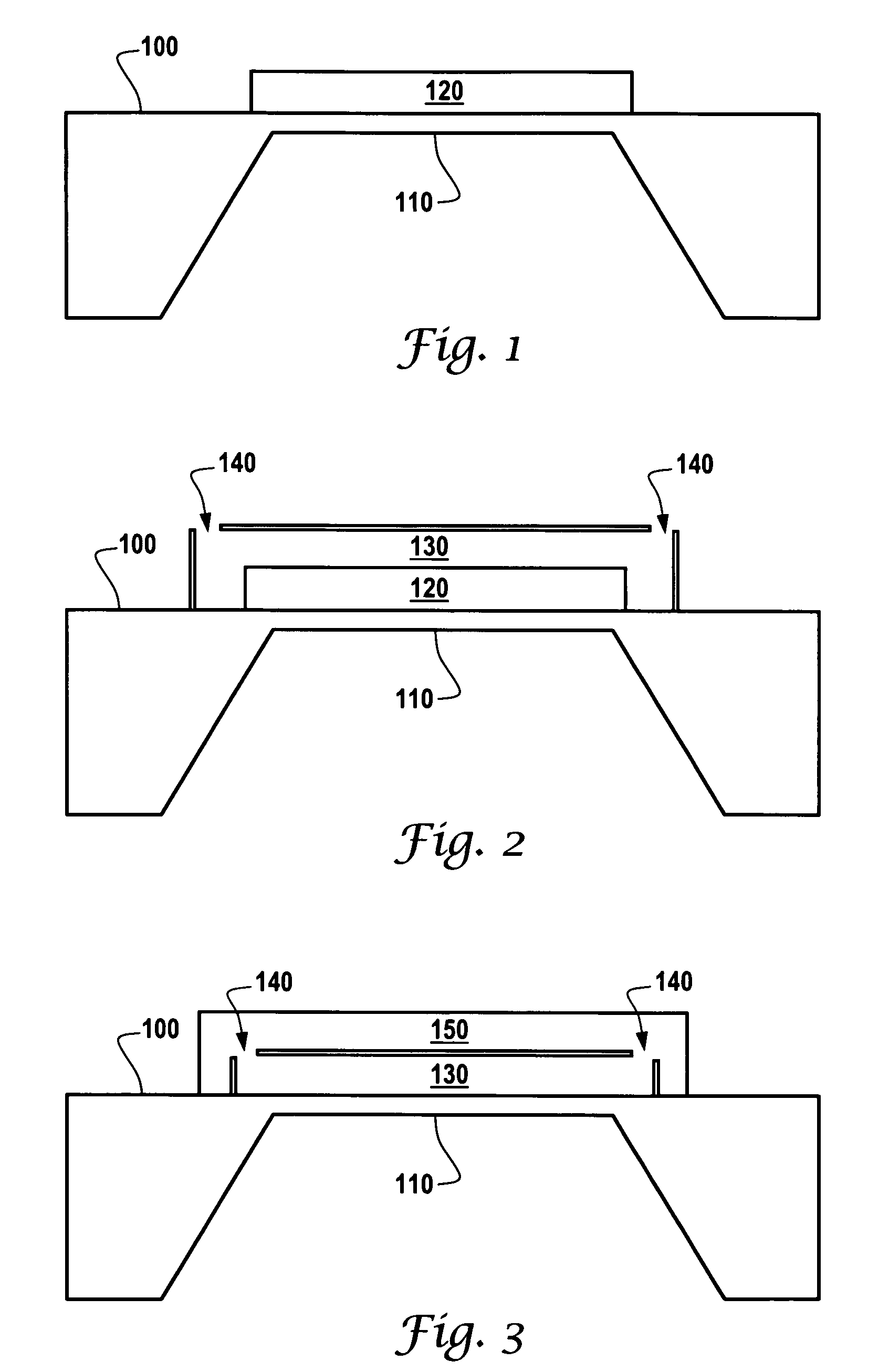
[0011]Referring to FIG. 1, a silicon substrate 100 has a diaphragm 110 formed using methods known by those skilled in the art. The diaphragm 110 includes a bottom surface where the media pressure to be measured is applied. A first layer 120 is formed on / deposited over the topside surface. The area of the first layer 120 is patterned to be larger than the diaphragm 110 area.
[0012]Referring to FIG. 2, another feature of the present invention is illustrated. A second layer 130 is formed on / deposited over the first layer 120. The area of the second layer 130 is patterned to be greater than the area of the first layer 120 and is a different material than the first layer 120. As shown in FIG. 2, holes 140 are formed / etched in the second layer 130. The holes allow the first layer 120 to be removed from under the second layer using methods known to those skilled in the art.
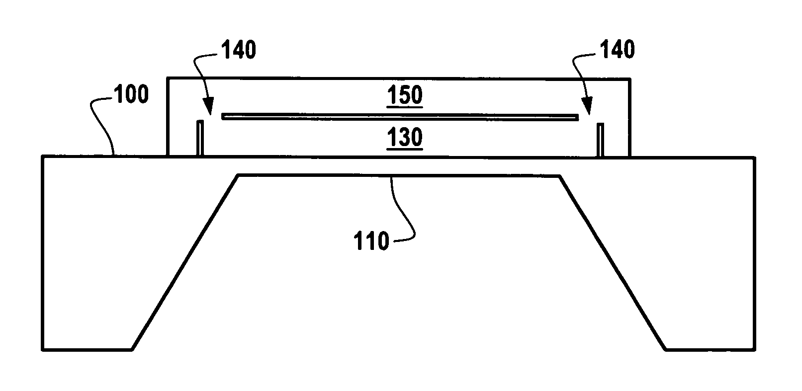
[0013]Referring to FIG. 3, another feature of the present invention is illustrated. As shown in FIG. 3, a third layer 1...
PUM
Property
Measurement
Unit
perimeter
aaaaa
aaaaa
area
aaaaa
aaaaa
pressure
aaaaa
aaaaa
Abstract
A pressure sensor includes a silicon diaphragm having bottom and topside surfaces. The bottom surface has been formed using methods known to those skilled in the art. A first layer is formed and patterned on the topside surface of the diaphragm having an area larger than the diaphragm. A second layer is formed and patterned over the first layer, the second layer being larger in area than the first layer. Holes formed in the second layer are used to remove the first layer using methods known to those skilled in the art. A third layer is formed and patterned over the second layer. The third layer seals the holes in the second layer creating a sealed cavity with a reference pressure on the topside surface of the diaphragm. During operation, media is applied to the bottom surface of the diaphragm wherein the media pressure can be sensed by the pressure sensor in relation to the reference pressure sealed on the topside of the diaphragm.
Description
FIELD OF THE INVENTION[0001]The present invention is generally related to pressure sensors. More particularly, the present invention is related to silicon-based absolute pressure sensors, used with corrosive media such as auto exhaust fumes, sensors that are made more robust by exposing the silicon backside of the sensor's diaphragm to the media rather than the top side.BACKGROUND[0002]Pressure sensors find wide use in industry: U.S. Pat. No. 6,452,427, U.S. Pat. No. 6,445,053, U.S. Pat. No. 6,229,190, U.S. Pat. No. 6,167,763, U.S. Pat. No. 6,112,598, U.S. Pat. No. 5,808,210, U.S. Pat. No. 5,747,705, U.S. Pat. No. 5,585,311, U.S. Pat. No. 5,535,135, U.S. Pat. No. 5,528,452, U.S. Pat. No. 5,459,351, U.S. Pat. No. 5,453,628, U.S. Pat. No. 5,155,061 U.S. Pat. No. 4,098,133, U.S. Pat. No. 4,008,619.[0003]The topside of a typical pressure sensor includes implanted piezoresistors to convert the pressure to an electrical signal, contacts to metal interconnections and bond pads used for wir...
Claims
Application Information
Patent Timeline
Application Date:The date an application was filed.
Publication Date:The date a patent or application was officially published.
First Publication Date:The earliest publication date of a patent with the same application number.
Issue Date:Publication date of the patent grant document.
PCT Entry Date:The Entry date of PCT National Phase.
Estimated Expiry Date:The statutory expiry date of a patent right according to the Patent Law, and it is the longest term of protection that the patent right can achieve without the termination of the patent right due to other reasons(Term extension factor has been taken into account ).
Invalid Date:Actual expiry date is based on effective date or publication date of legal transaction data of invalid patent.