Fuel injection device and adjustment method thereof

a technology of fuel injection and adjustment method, which is applied in the direction of electrical control, process and machine control, instruments, etc., can solve the problem that the device has a difficulty in sensing the pressure fluctuation caused by the injection with high accuracy, and achieve the effect of high accuracy and high accuracy

Active Publication Date: 2008-09-18
DENSO CORP
View PDF29 Cites 184 Cited by
  • Summary
  • Abstract
  • Description
  • Claims
  • Application Information

AI Technical Summary

Benefits of technology

[0015]In contrast, the device according to the invention can directly measure a pressure value before the attenuation by use of the above-mentioned fuel passage pressure sensor. Thus, the injection characteristics such as the transition of the injection rate and the injection quantity associated with the predetermined injection can be detected with higher accuracy by directly determining the transition of the injection rate and the injection quantity from the measured pressure value than the structure using the differential value.
[0016]According to another aspect of the present invention, a fuel injection device for detecting a fuel injection pressure in a common rail type fuel injection system of an engine has a fuel pressure serially obtaining device for serially obtaining fuel pressure signals of an injector connected to a common rail at intervals short enough to draw a tra

Problems solved by technology

Thus, this device has a difficulty in sensing the pressur

Method used


Image

  • Fuel injection device and adjustment method thereof
  • Fuel injection device and adjustment method thereof
  • Fuel injection device and adjustment method thereof

Examples


Embodiment Construction

[0056]Now, an embodiment embodying a fuel injection device and an adjustment method thereof according to the invention will be described with reference to the accompanying drawings. The device of this embodiment is mounted on a common rail type fuel injection system (high-pressure injection fuel supply system) which controls a reciprocating diesel engine serving as an engine for a vehicle, for example. That is, the device of this embodiment is also a fuel injection device for a diesel engine which is used in directly injecting and supplying the high-pressure fuel (for example, light oil at an injection pressure of about 1400 atmospheres) to a combustion chamber in an engine cylinder of the diesel engine (internal combustion engine), like the device as disclosed in the above-mentioned Patent Document 1.

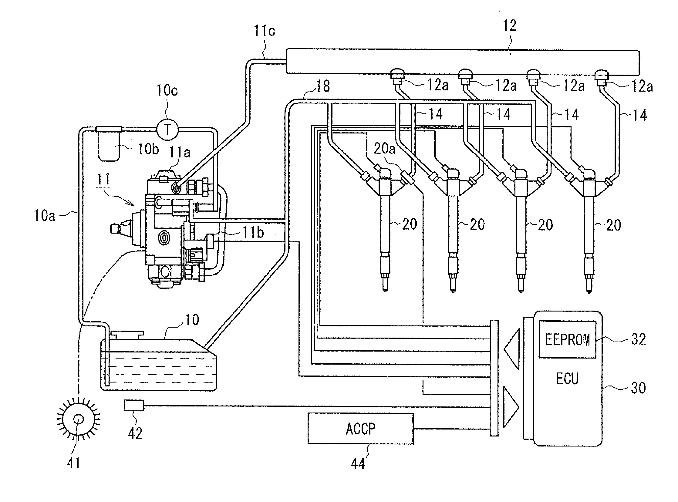
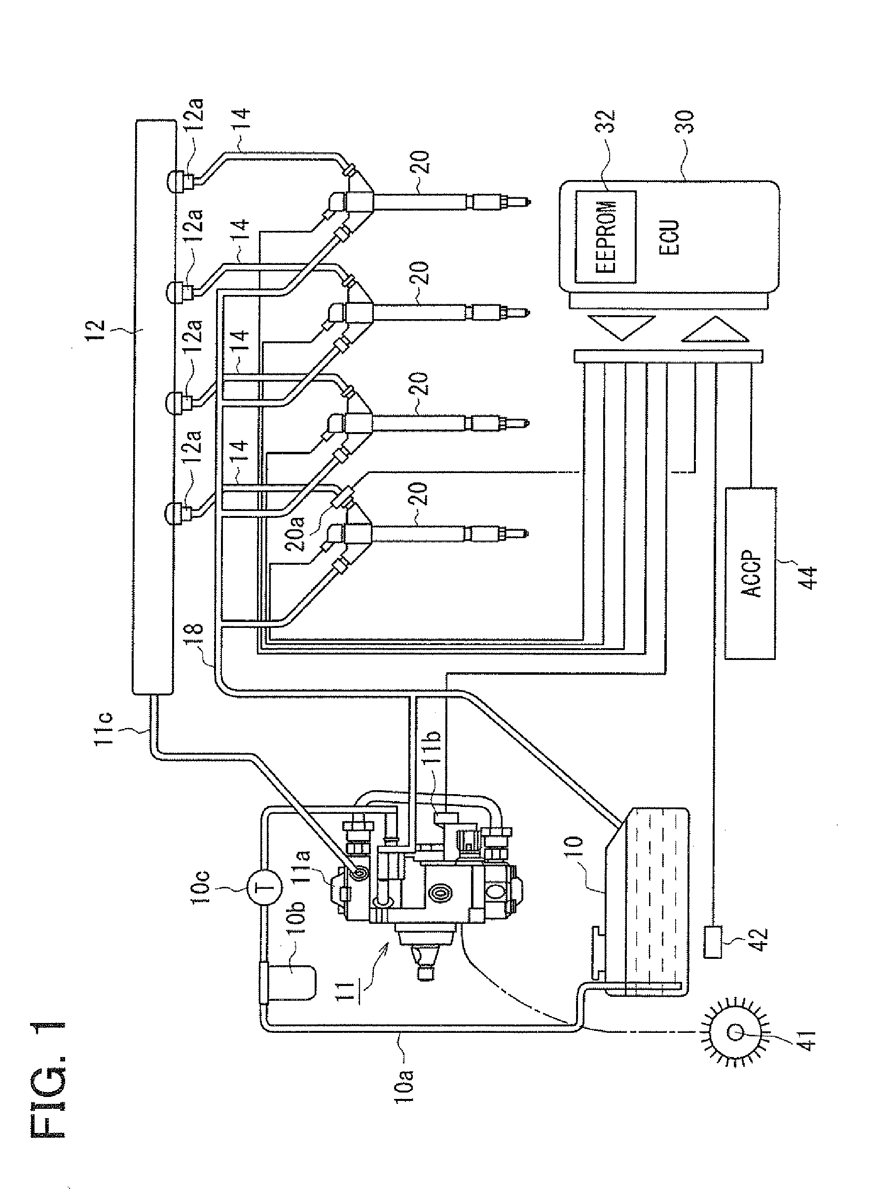
[0057]Now, the outline of the common rail type fuel injection system according to this embodiment will be described with reference to FIG. 1. As the engine of this embodiment, a multi-...


PUM


Abstract

A fuel injection device (fuel supply system) of a common rail type fuel injection system for an engine includes a pressure sensor disposed in a fuel inlet of an injector for measuring a fuel pressure at a position where the sensor is disposed and an ECU for sensing various kinds of pressure fluctuations associated with the injection including a pressure leak due to an injection operation of the injector and waving characteristics due to actual injection thereof based on sensor outputs from the pressure sensor. The ECU serially obtains the sensor outputs from the pressure sensor at intervals of 20 μsec.

Description

CROSS REFERENCE TO RELATED APPLICATION[0001]This application is based on and incorporates herein by reference Japanese Patent Applications No. 2006-307399 filed on Nov. 14, 2006 and No. 2007-210259 filed on Aug. 10, 2007.BACKGROUND OF THE INVENTION[0002]1. Field of the Invention[0003]The present invention relates to a fuel injection device constituting a common rail type fuel injection system of an engine and to an adjustment method thereof. More particularly the invention relates to a fuel injection device for detecting a fuel injection pressure in the system and to an adjustment method thereof.[0004]2. Description of Related Art[0005]Such a device has been known, for example, as described in Patent Document 1 (JP-A-H10-220272). In the common rail type fuel injection system having the fuel injection device, fuel pumped by a fuel pump is accumulated by a common rail in a high-pressure state. The accumulated high-pressure fuel is supplied to respective injectors of cylinders via pipe...

Claims


Application Information

Patent Timeline
IPC IPC(8): F02D3/00G01M15/09G06F17/00F02M69/54
CPCF02D41/3809F02D41/3836F02D41/402F02D2200/0602F02D2200/0616F02D2250/04F02D2250/14F02M47/027F02M57/005F02M2200/24G01M15/09Y02T10/40
Inventor ISHIZUKA, KOUJINAKATA, KENICHIROUTAKEUCHI, KATSUHIKO
Owner DENSO CORP
Why Eureka
Try Eureka