Attachment control device

a control device and attachment technology, applied in the field of power machines, can solve problems such as the opening of opposing control valves, and the disassembly of control valves

Inactive Publication Date: 2005-08-02
CLARK EQUIP CO INC
View PDF28 Cites 109 Cited by
  • Summary
  • Abstract
  • Description
  • Claims
  • Application Information

AI Technical Summary

Problems solved by technology

Depending on the particular type of attachment or attachments mounted on the skid steer loader, certain functions may be disabled or unusable.
Further, depending on the particular type of attachment or attachments mounted on the skid steer loader, certain combinations of inputs from the operator input devices, when performed simultaneously, can result in opposing control valves being opened.

Method used


Image

  • Attachment control device
  • Attachment control device
  • Attachment control device

Examples


Embodiment Construction

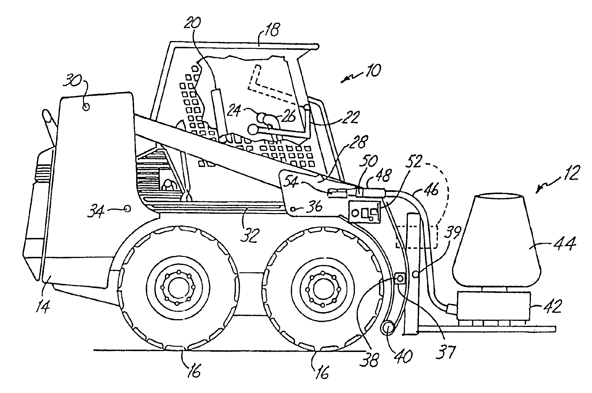
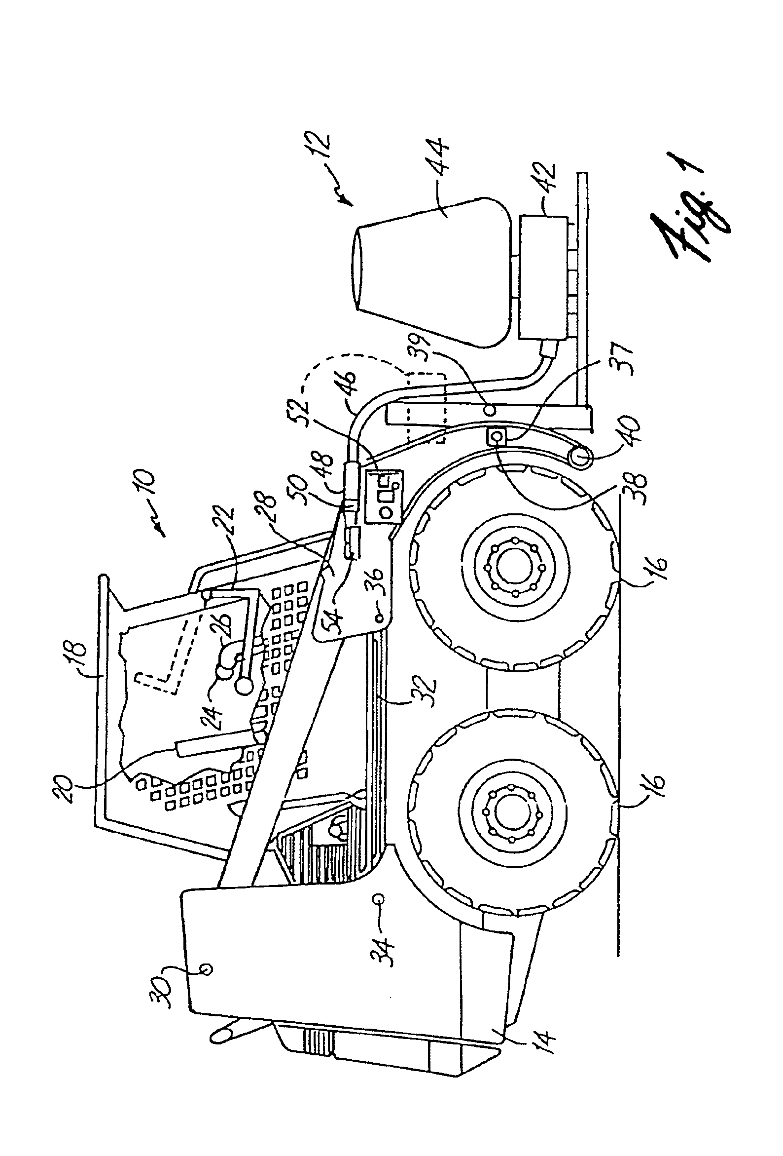
[0016]FIG. 1 is a side elevational view of a skid steer loader 10 having an attachment 12 in accordance with one aspect of the present invention. Skid steer loader 10 includes a frame 14 supported by wheels 16. Frame 14 also supports a cab 18 which defines an operator compartment and which substantially encloses a seat 20 on which an operator sits to control skid steer loader 10. A seat bar 22 is pivotally coupled to a portion of cab 18. When the operator occupies seat 20, the operator then pivots seat bar 22 from the raised position (shown in phantom in FIG. 1) to a lowered position shown in FIG. 1. Cab 18 also typically includes a pair of control levers 24 and 26 with associated hand grips. Control levers 24 and 26 include actuable inputs (such as rocker switches, buttons or other operator input devices) for providing input signals.

[0017]A lift arm 28 is coupled to frame 14 at pivot points 30. A pair of hydraulic cylinders 32 (only one of which is shown in FIG. 1) are pivotally co...


PUM


Abstract

The present invention provides an attachment for use with a power machine. An attachment control device includes a controller, such as a microprocessor, a microcontroller or other digital computer which senses the type of attachment and controls power to the attachment accordingly. In one embodiment, the attachment control device can be used for remotely controlling the attachment and includes an ignition switch and a stop switch and allows a user to operate the attachment from outside the operator compartment of the power machine, when the power machine is started from the attachment control device.

Description

INCORPORATION BY REFERENCE[0001]The following patents are hereby fully incorporated by reference:[0002]U.S. Pat. No. 5,425,431, issued Jun. 20, 1995, entitled “INTERLOCK CONTROL SYSTEM FOR POWER MACHINE,” is incorporated herein by reference; and[0003]U.S. Pat. No. 5,577,876, issued Nov. 26, 1996, entitled “HYDRAULIC INTERLOCK SYSTEM,” is incorporated herein by reference, both assigned to the same assignee as the present invention.[0004]Reference is also made to co-pending U.S. patent application Ser. No. 09 / 130,986, entitled “REMOTE ATTACHMENT CONTROL DEVICE FOR POWER MACHINE,” filed Aug. 7, 1998.BACKGROUND OF THE INVENTION[0005]The present invention deals with a power machine. More specifically, the present invention deals with a power machine having an attachment with a control device for controlling the attachment.[0006]Power machines, such as skid steer loaders, typically have a frame which supports a cab or an operator compartment and a movable lift arm which, in turn, supports...

Claims


Application Information

Patent Timeline
Patent Type & Authority Patents(United States)
IPC IPC(8): E02F9/24E02F3/42E02F3/43E02F9/20
CPCE02F3/3695E02F3/431E02F9/2025E02F9/24
Inventor ROSSOW, SCOTT R.BRANDT, KENNETH A.KACZMARSKI, WALLY L.
Owner CLARK EQUIP CO INC
Why Eureka
Try Eureka