Horizontal feed mixer and method for using same

Active Publication Date: 2005-08-02
ROTO MIX
View PDF14 Cites 26 Cited by
  • Summary
  • Abstract
  • Description
  • Claims
  • Application Information

AI Technical Summary

Benefits of technology

[0012]Shear bars are provided adjacent one of the augers and adjacent the rotor so as to i

Problems solved by technology

However, one difficulty encountered with horizontal feed mixers is the ability to

Method used


Image

  • Horizontal feed mixer and method for using same
  • Horizontal feed mixer and method for using same
  • Horizontal feed mixer and method for using same

Examples


Example

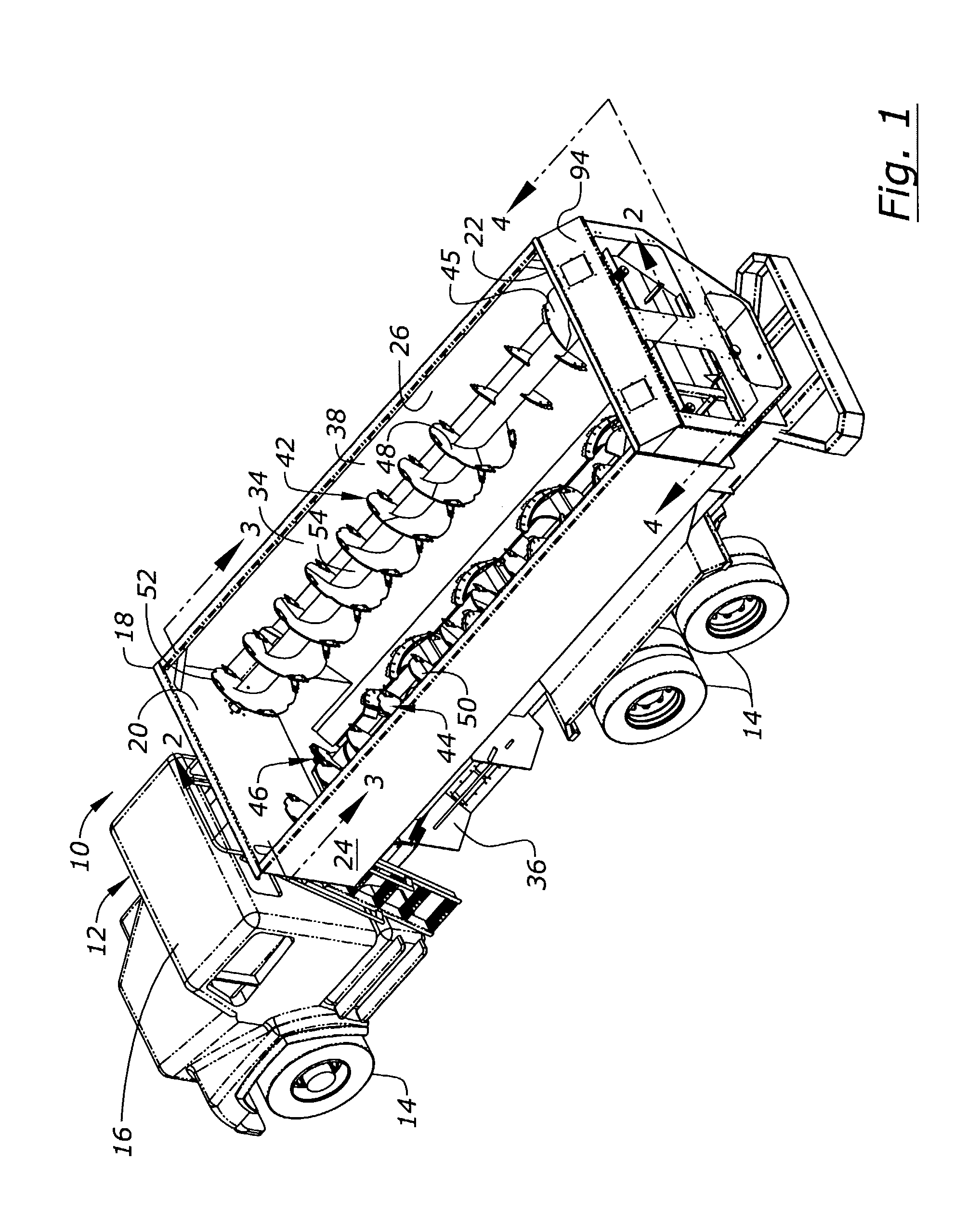
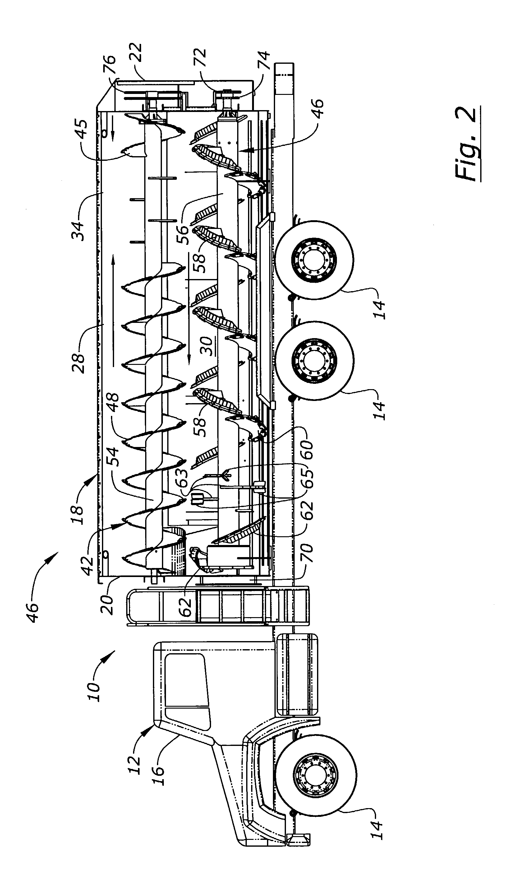
[0023]Referring to the drawings the numeral 10 refers generally to the feed mixer of the present invention. Mixer 10 is mounted on a truck 12, but it could just as easily be mounted upon a wagon frame or a stationary frame rather than a truck frame. Truck 12 includes wheels 14 a cab 16 and a mixing box 18 mounted thereon.

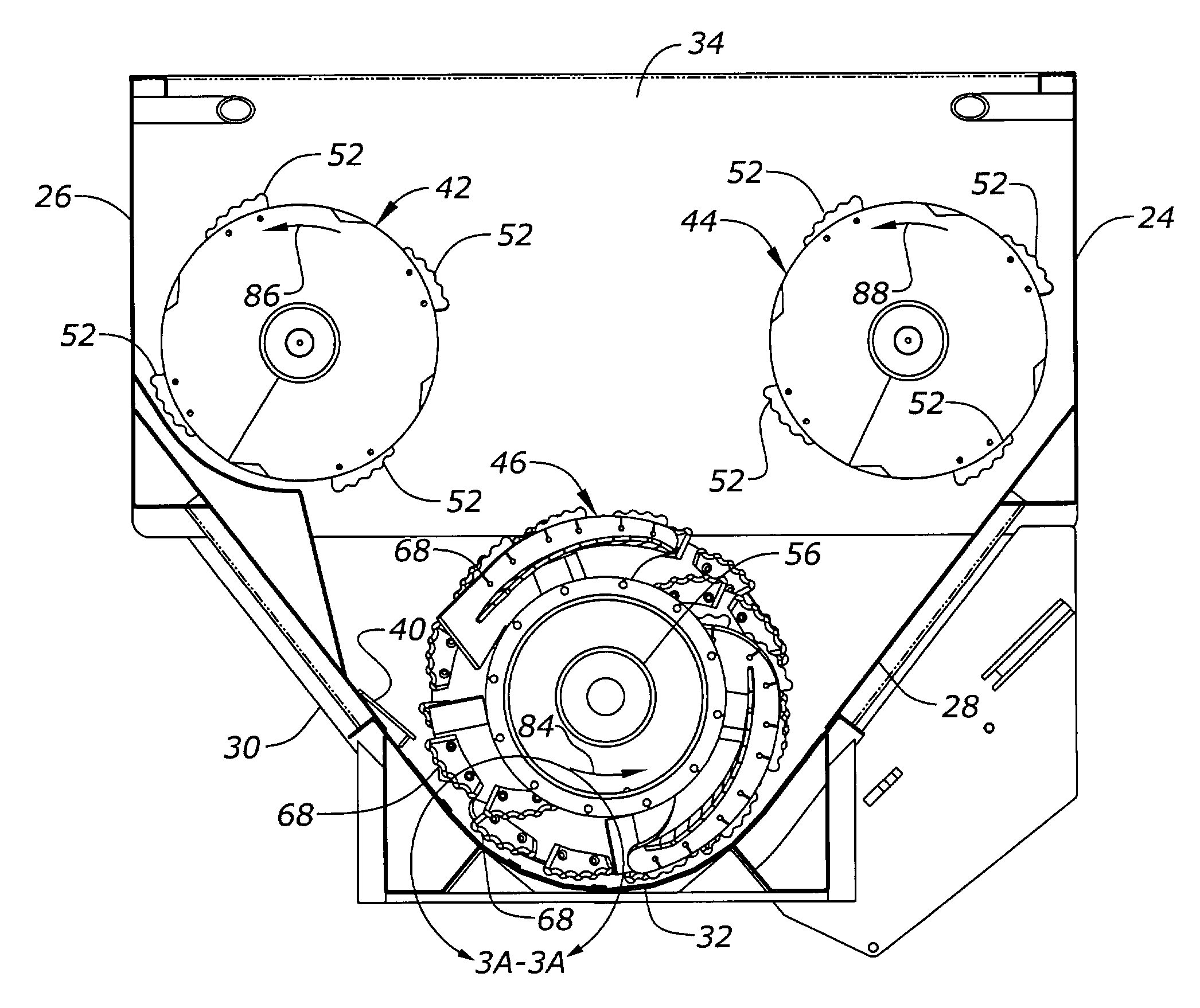
[0024]The mixing box includes a front wall 20, a rear wall 22, first and second vertical side walls 24, 26 (FIG. 3) and first and second inclined side walls 28, 30. Inclined side walls 28, 30 are joined at their lower ends by a curved apex 32 which is curved to conform to the rotor which will be described more full hereinafter. The mixing box 18 defines a mixing chamber 34 having an open upper end. Mixing box 18 also includes a discharge door 36 of conventional construction mounted on one of the side walls of the mixing box. The discharge door 36 can be lowered and opened to create a chute for discharging material from the mixer in conventional fashion. An additiona...


PUM


Abstract

The feed mixer of the present invention includes two upper horizontal augers having flighting thereon. Below and between the two upper augers is a rotor having helical paddle segments thereon. The two upper augers and the rotor all rotate in the same direction, but the two upper augers force material in one direction and the lower rotor forces material in the opposite direction. Knives on the outer edges of the upper augers and on the helical segments of the rotor act upon the hay to cut it and facilitate its mixing with other feed ingredients.

Description

CROSS-REFERENCE TO RELATED APPLICATIONS[0001]This application claims benefit under 35 U.S.C. § 119(e) of provisional application 60 / 390,736 filed Jun. 21, 2002.BACKGROUND OF THE INVENTION[0002]The present invention relates to a horizontal feed mixer and method for processing hay bales. Specifically the present invention provides an apparatus and method for continuous processing of hay bales, mixing hay with other feed ingredients into a total mixed ration, and / or processing only hay bales, either in batches or continuously.[0003]Various types of horizontal feed mixers have been provided. However, one difficulty encountered with horizontal feed mixers is the ability to process an entire bale without first chopping up the bale into smaller particles. This is particularly advantageous with the larger feed mixers where it is desirable to place an entire large round or square bale into the mixing box for mixing hay with other feed ingredients.[0004]Therefore, a primary object of the pres...

Claims


Application Information

Patent Timeline
IPC IPC(8): A01K5/00B01F15/00B01F13/00B01F13/10B01F7/02B01F7/08B01F7/00
CPCA01K5/002B01F7/00008B01F7/081B01F13/0035B01F13/1044B01F13/105B01F2013/108Y10S241/605Y10S366/603B01F27/05B01F27/721B01F33/502B01F33/8305B01F33/833B01F33/83611
Inventor NEIER, BENJAMIN R.NEIER, RODNEY R.REIMER, GREGORY R.WHITAKER, BRENT H.COOKSEY, MARK T.CASALE, CELSO LUIS
Owner ROTO MIX
Why Eureka
Try Eureka