
Implantable expandable medical devices having regions of differential mechanical properties and methods of making same

a technology of differential mechanical properties and medical devices, applied in the field of implantable expandable medical devices, can solve the problems of inability to recover the cardiac region from a deformation event, and achieve the effect of minimizing unwanted vascular injuries

Inactive Publication Date: 2005-08-02
VACTRONIX SCI LLC
View PDF24 Cites 114 Cited by
  • Summary
  • Abstract
  • Description
  • Claims
  • Application Information

AI Technical Summary

Benefits of technology

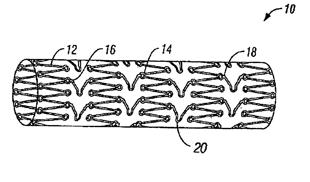
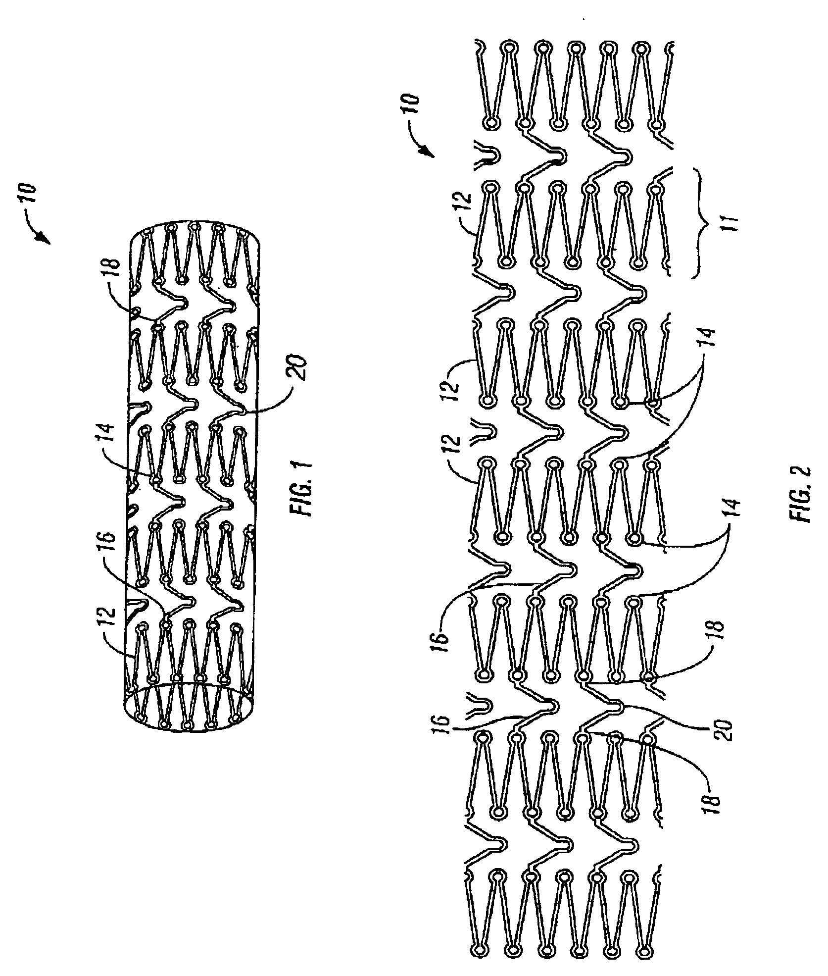
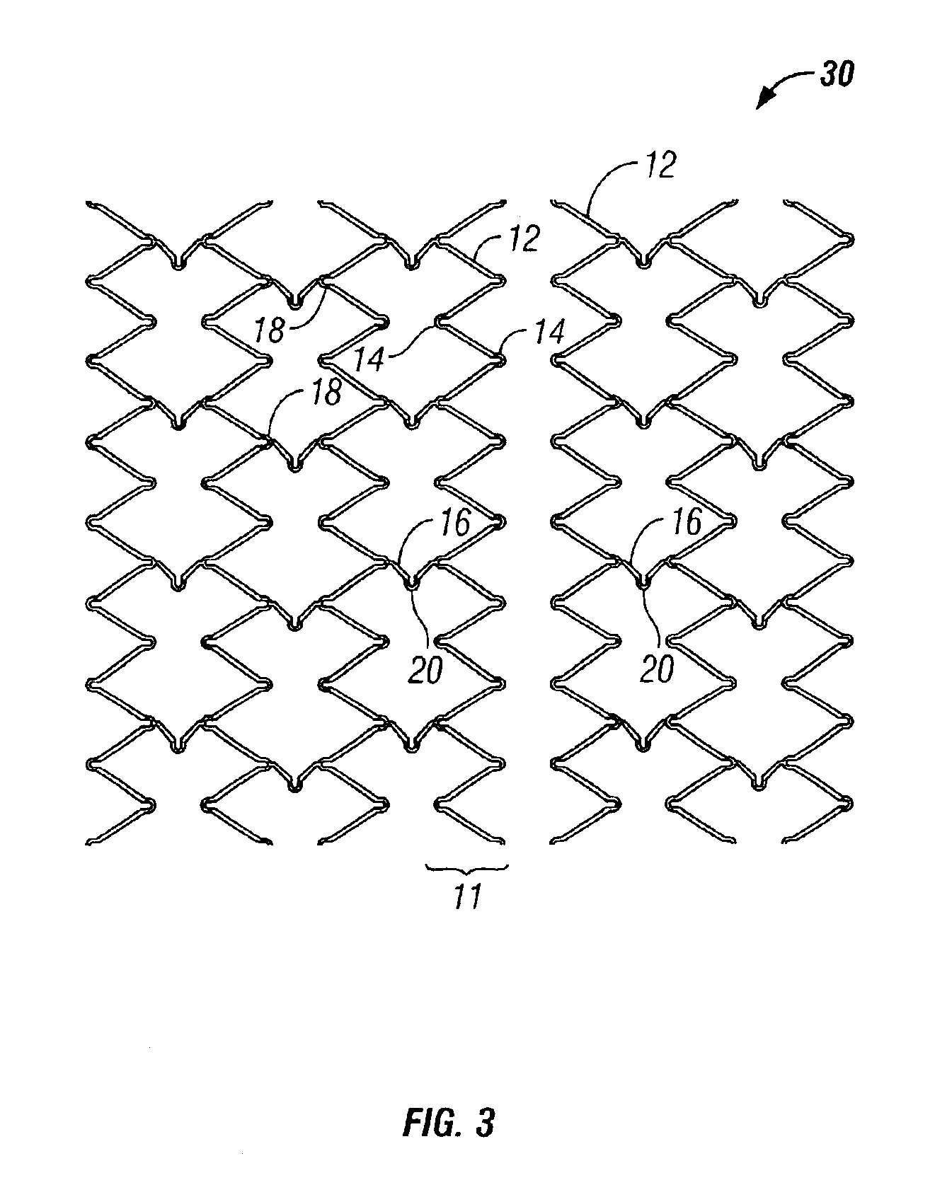
[0018]In the case of a stent, stent-graft, covered stent, or graft, for example, each of which must have the ability to be circumferentially expandable in vivo and longitudinally flexible for endoluminal delivery. Circumferentially expansive structural members may be formed of elastic, pseudoelastic or superelastic materials, have regions, such as hinge or articulation regions, that permit elastic, pseudoelastic or superelastic expansion of the circumferentially expansive structural members. Alternatively, the circumferentially expansive structural members may have regions having an Af value less than body temperature (i.e., 37° C.) or be sufficiently close to body temperature to behave elastically or pseudoelastically in vivo. Longitudinal flexibility is imparted by providing a series of longitudinal members that interconnect adjacent pairs of circumferentially expansive structural members.
[0023]The plurality of expansion hinges, the plurality of longitudinal flexion hinges and the plurality of intermediate hinges may all have different material and / or mechanical properties from one another or from the strut members. For example, in accordance with one embodiment of the invention, the interconnection member hinges are made sufficiently martensitic so that they pseudoplastically deform permitting non-recoverable longitudinal flexion of the device, thereby minimizing unwanted vascular injury, and the expansion hinges are sufficiently austenitic, so that permit self-expansion of the device.

Problems solved by technology

The martensitic regions are sufficiently martensitic such that the martensitic regions do not recover from a deformation event under in vivo conditions.

Method used


Image

  • Implantable expandable medical devices having regions of differential mechanical properties and methods of making same
  • Implantable expandable medical devices having regions of differential mechanical properties and methods of making same
  • Implantable expandable medical devices having regions of differential mechanical properties and methods of making same

Examples


Embodiment Construction

[0031]The present invention pertains generally to self-expanding endoluminal devices and methods for their production, and more particularly to implantable self-expanding medical devices, such as endoluminal stents, having a generally tubular configuration formed of a plurality of structural support members in which geometric deformation of the plurality of structural support members causes a geometric expansion of the implantable medical device.

[0032]The endoluminal devices are made of biocompatible metals or pseudometals. Preferably, the endoluminal devices are fabricated so that they exhibit circumferential self-expansion, plastic or pseudoplastic flexibility in the longitudinal axis of the device and have negligible longitudinal elastic recoil, i.e., less than 20%, when the device is flexed along its longitudinal axis. Suitable biocompatible materials for use with the present invention include, for example, titanium, vanadium, aluminum, nickel, tantalum, zirconium, chromium, sil...


PUM


Abstract

An implantable expandable medical device in which selected regions of the device are in a martensite phase and selected regions are in an austenite phase. The martensitic regions exhibit pseudoplastic behavior in vivo and may be deformed without recovery under in vivo body conditions. In contrast the austenitic regions exhibit superelastic behavior in vivo and will recover their pre-programmed configuration upon deformation or release of an applied strain

Description

BACKGROUND[0001]The present invention relates generally to implantable expandable medical devices and more particularly to implantable endoluminal stents, covered-stents, stent-grafts and grafts employed to restore and maintain patency of anatomical passageways within a mammalian body. The dramatic success enjoyed by a variety of endoluminal implantable medical devices has largely been the result of their ability to be delivered utilizing minimally invasive techniques that significantly reduce the trauma to the patient. While there are many types of endoluminally-delivered implantable medical devices, the present invention relates specifically to generally tubular devices that are expandable from a first smaller diameter suitable for minimally invasive delivery to a second enlarge diameter suitable for restoring and maintaining patency of the anatomical passageway.[0002]The most prevalent type of implantable expandable endoluminal device is the stent. Stents are typically used to tr...

Claims


Application Information

Patent Timeline
IPC IPC(8): A61F2/06A61L31/14A61L31/02A61F2/00A61F2/90
CPCA61L31/022A61L31/14A61F2/91A61F2/915A61F2/89A61F2002/91541A61F2002/91558A61F2210/0023A61F2250/0042A61F2210/0014A61F2220/0091A61F2002/91575
Inventor BOYLE, CHRISTOPHER T.BANAS, CHRISTOPHER T.MARTON, DENES
Owner VACTRONIX SCI LLC
Learn More