Eureka AIR delivers breakthrough ideas for toughest innovation challenges, trusted by R&D personnel around the world.

Image processor

Inactive Publication Date: 2005-08-02
PANASONIC CORP
View PDF6 Cites 19 Cited by
  • Summary
  • Abstract
  • Description
  • Claims
  • Application Information

AI Technical Summary

Benefits of technology

[0020]The invention solves these problems and aims at providing an image processor which performs ROP processing on a device color without causing degradation of picture quality.
[0021]According to first aspect of the invention, an image processor comprises: color conversion means for converting an input signal to color signals of at least four colors; gamma correction means for performing gamma correction on the color signals; binarization means for binarizing the color signals through comparison with a threshold value; superimposing means for superimposing a color signal of at least one color out of the binarized color signals on another color signal to convert the signals to a superimposed color signal; logical operation means for performing a logical operation previously defined for an image of three or fewer colors on the superimposed color signal; and separation means for separating color signals as an output of the logical operation means into separated color signals of at least four colors. It is thus possible to provide an image processor capable of correctly executing a logical operation previously defined for an image of three or fewer colors on an image of at least four colors.
[0022]According to second aspect of the invention, the binarization means comprises a threshold matrix having a cyclicity for binarization and that the separation means determines whether the superimposed signal has the cyclicity of the threshold matrix used by the binarization means and generates separated color signals based on the determination result. It is thus possible to separate a temporarily superimposed image without causing picture quality degradation thereby obtaining a quality output image.
[0023]According to third aspect of the invention, the output signals of the color conversion means correspond to four colors cyan, magenta, yellow and black, that the superimposing means obtains the logical sum of a black pixel,with pixels of cyan, magenta and yellow to output the superimposed color signal as three colors cyan, magenta and yellow, and that the separation means separates an image of cyan, magenta, yellow and black from the pixels of cyan, magenta and yellow. It is thus possible to provide an image processor capable of correctly executing a logical operation previously defined for an image of three or fewer colors on four device colors cyan, magenta, yellow and black.

Problems solved by technology

This result is accompanied by numerous problems including: (1) The black color comprising three toner colors appears more chromatic; (2) A slight displacement in the print position of each color results in a black image surrounded by colors; (3) The total volume of toner is large so that transfer is unsuccessful in a printing process; (4) Fused toner comes off in scales; and (5) Toner three times as much as that required elsewhere is used, which is uneconomical.
This leads to insufficient latent image formation so that small dots are degenerated, shrink, or may disappear.
This method has problems: when for example a rectangular image in a color is on a white background, the black density differs between a case where a small region is provided inside the rectangle and a case where a small region is provided across a rectangular edge sections, so that the black density may not be detected correctly for the same color.
The black density in this region increases and the above problem will result, in case the region includes characters or a line drawing in black.

Method used


Image

  • Image processor
  • Image processor
  • Image processor

Examples


embodiment 1

(Embodiment 1)

[0045]An embodiment of the invention is described referring to FIGS. 1 through 11. Connection form of a host computer and a color printer as well as the configuration and operation of the color printer are same as those described with respect to the related art so that the corresponding description is omitted.

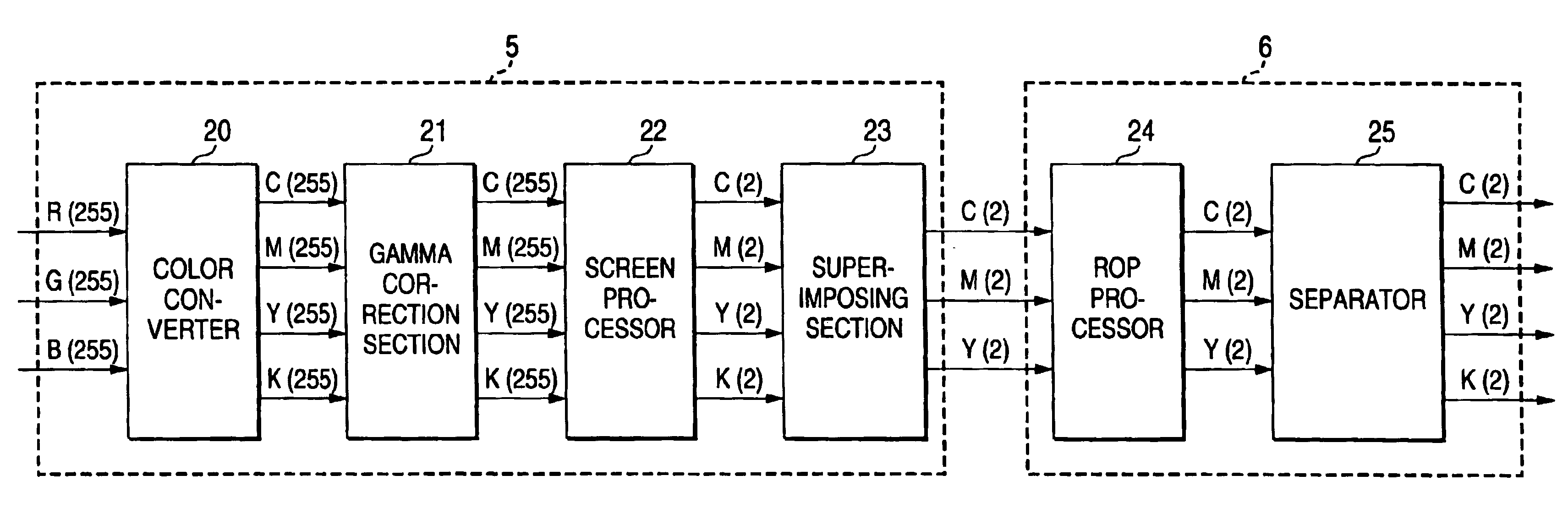
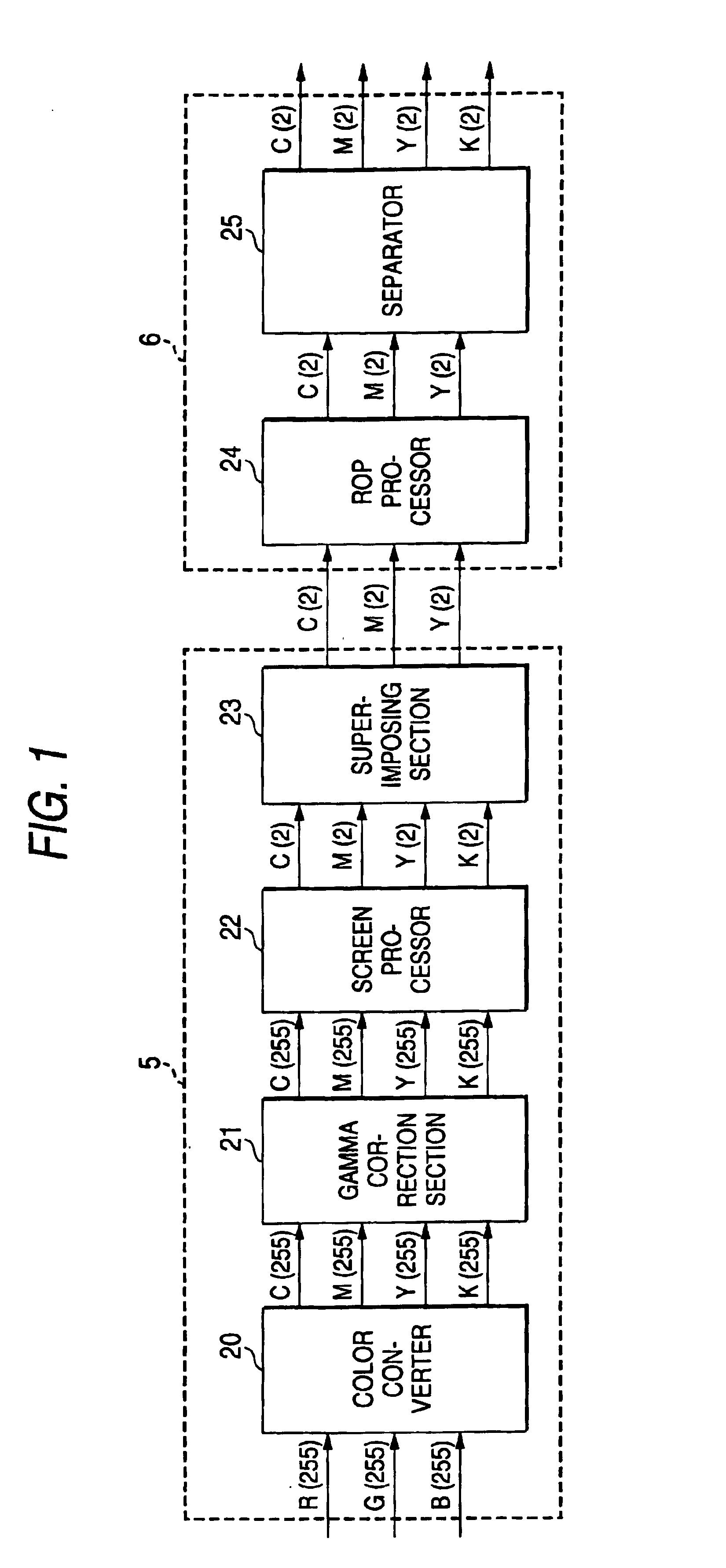
[0046]FIG. 1 illustrates an image processor according to the invention.

[0047]A numeral 20 designates a color converter for converting RGB color signals to CMYK color signals, 21 a gamma correction section for correcting engine output characteristics, 22 a screen processor for comparing an image with a threshold matrix and binarizing the image, 23 a superimposing section for superimposing a K image on CMY pixels, 24 an ROP processor for performing ROP processing, and 25 a separator for separating a K component image from a CMY image to generate a CMYK image.

[0048]The functional blocks of the image processor in FIG. 1 is divided into the interpreter 5 and the raster...


PUM


Abstract

An image processor includes: a color conversion unit for converting an input signal to color signals of at least four colors; a gamma correction unit for performing gamma correction on the color signals; a binarization unit for binarizing the color signals through comparison with a threshold value; a superimposing unit for superimposing a color signal of at least one color but of the binarized color signals on another color signal to convert the signals to a superimposed color signal; logical operation unit for performing a logical operation previously defined for an image of three or fewer colors on the superimposed color signal; and a separator for separating color signals as an output of the logical operation unit into separated color signals of at least four colors.

Description

CROSS REFERENCE TO RELATED APPLICATION[0001]This application is based upon and claims the benefit of priority of Japanese Patent Application No. P2002333381 filed on Nov. 18, 2002, the contents of which are incorporated herein by reference in its entirety.BACKGROUND OF THE INVENTION[0002]The present invention relates to an image processor used for image formation on a color printer which employs electronic photography.[0003]In recent years, more and more color images have been printed by printers in offices and homes in line with widespread use of computers and color printers.[0004]FIG. 12 illustrates the connection form of a host computer 50 and a color printer 1. The color printer 1 is connected to the host computer 50 via an interface 53 such as IEEE1284, or a network such as a LAN 51 and the internet 52. The color printer 1 and the host computer 50 communicate print data and printer status information with each other.[0005]FIG. 13 is a block diagram of the printer. A numeral 2 d...

Claims


Application Information

Patent Timeline
IPC IPC(8): B41J2/525B41J5/30G06T1/00G09G5/02G06F3/12H04N1/52H04N1/46H04N1/60
CPCH04N1/52H04N1/6022
Inventor NISHIDA, YUKIHIROHIRATSUKA, SEIICHIRO
Owner PANASONIC CORP
Why Eureka
Eureka Blog
Learn More