Dynamic zero clearance exhausting EMC sealing system

a sealing system and zero clearance technology, applied in the direction of sliding card holders, electrical apparatus contruction details, standard structures, etc., can solve the problems of thermal damage and/or noise within the circuit, concomitant increase in power density and heat dissipation, and additional packaging design constraints

Active Publication Date: 2005-08-02
LENOVO GLOBAL TECH INT LTD
View PDF16 Cites 13 Cited by
  • Summary
  • Abstract
  • Description
  • Claims
  • Application Information

AI Technical Summary

Problems solved by technology

With increased circuit density there has also been an additional constraint on packaging design.
As a result, any externally radiated heat from PCB's or components surrounding the smaller packaging is less likely to be dissipated, thus producing thermal damage and / or noise within the circuit and component with increased circuit density, there is also a concomitant increase in power density and heat dissipation.
There is an ever increasing problem of electromagnetic interference caused by such devices.
The problem has been exacerbated by the “improvement” in semiconductor devices which allows them to operate at higher speeds, generally causing emission in the higher frequency bands where interference is more likely to occur.

Method used


Image

  • Dynamic zero clearance exhausting EMC sealing system
  • Dynamic zero clearance exhausting EMC sealing system
  • Dynamic zero clearance exhausting EMC sealing system

Examples


Embodiment Construction

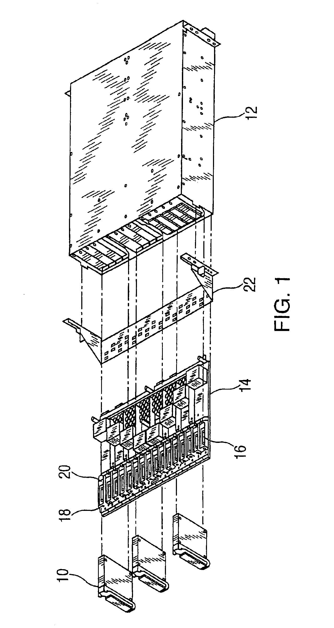
[0019]Referring generally to FIG. 1, a docking apparatus or cassette 10 for mounting a printed circuit card (PCC) into a computer system 12 is shown, in accordance with an embodiment of the invention. Docking apparatus 10 preferably provides structural support to the PCC so as to allow for the easy insertion and removal of the PCC from computer system 12, as well as thermal and electrical isolation from other PCC's and components within the computer system.

[0020]Docking cassette 10 is disposed onto a computer system main board 14 or main printed circuit board (PCB) having a PCB connector receptacle 16, a first receptacle 18 and a second receptacle 20. Docking cassette 10 is preferably disposed onto computer system main board 14 such that a PCB connector is adjacent to PCB connector receptacle 16. In addition, main board 14 is slidably engaged with a cable tray 22 for releasably supporting and securing computer system 12 in a system rack (not shown).

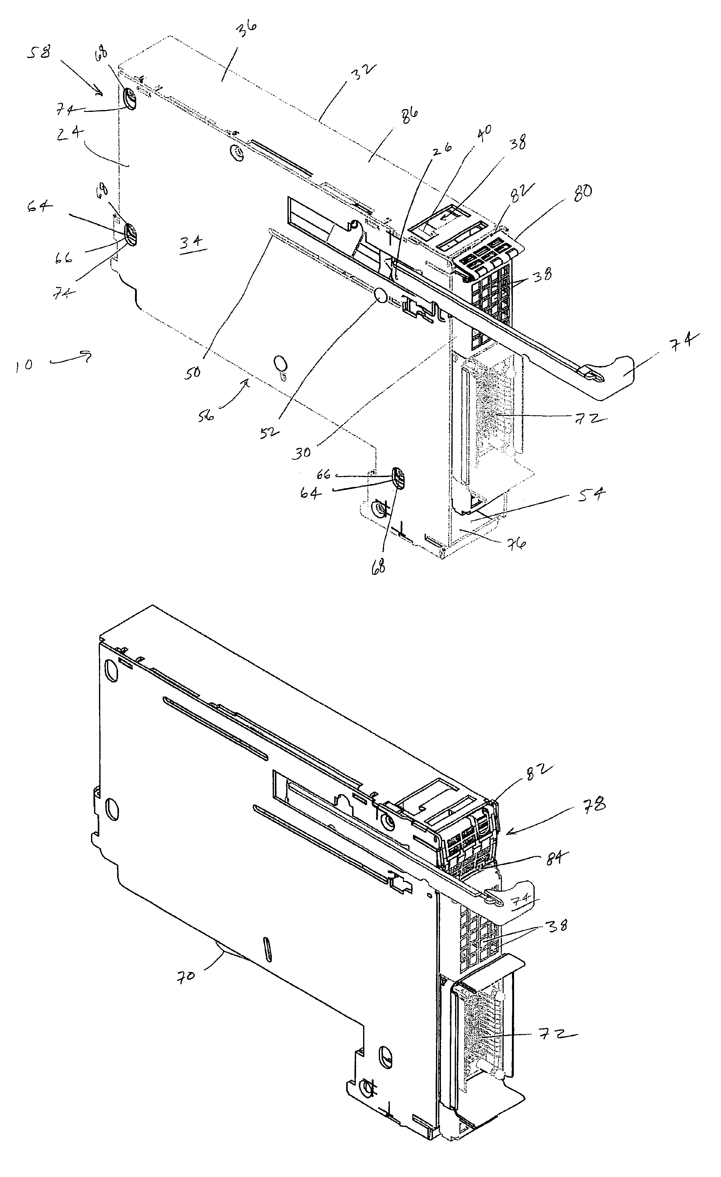
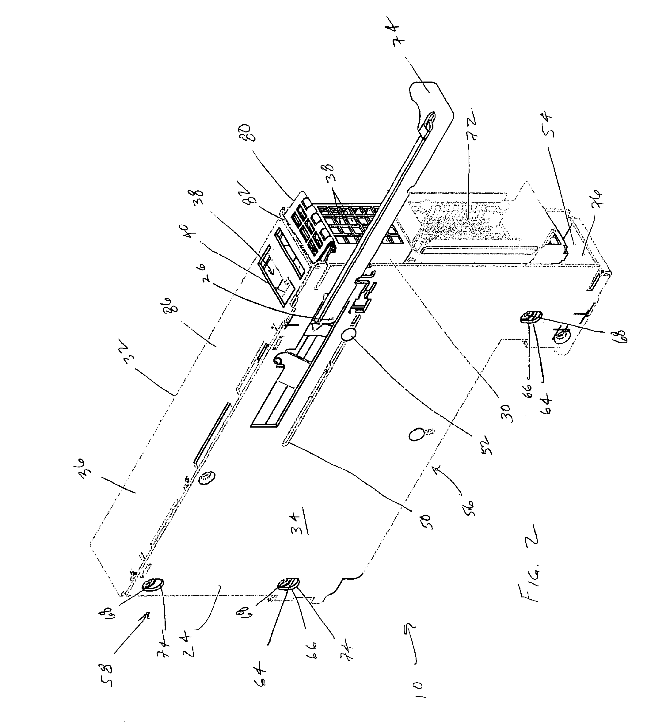
[0021]Referring to FIGS. 2 and 3, ...


PUM


Abstract

A docking apparatus for printed circuit boards including a cassette housing, having a housing base, a housing cover and a housing wall, wherein the housing base and the housing wall are disposed relative to each other so as to define a housing cavity for containing a printed circuit card and wherein the housing wall includes a cable opening disposed so as to be communicated with the housing cavity, a housing bezel, disposed relative to the cassette housing so as to be associated with the cable opening and translatable therein, the housing bezel is in electrical communication with the printed circuit card and translatable therewith when the printed circuit card is engaged and disengaged with a printed circuit board, and an EMC sealing device disposed between the housing bezel and the cassette housing, the EMC sealing device configured to provide a movable EMC seal proximate the cable opening while still allowing airflow therethrough while covering a portion of the cable opening created between the housing and the housing bezel upon translation of the bezel.

Description

FIELD OF THE INVENTION[0001]The present invention is generally directed to pluggable cartridges for inserting printed circuit cards into and for removing them from printed circuit boards. More particularly, the present invention is directed to a dynamic zero clearance exhausting EMC sealing system incorporated with the cartridge which provides a level of EMC shielding and thermal protection.BACKGROUND OF THE INVENTION[0002]The past twenty-five or so years have seen the development of ever smaller electrical circuit components at the chip level. However, to take fullest advantage of achievements in electrical circuit miniaturization, one must package the resultant printed circuit cards containing these chips in an efficient manner. Clearly, the packaging of printed circuit cards in tight spaces is a direct logical extension of increasing chip level circuit densities. It should also be noted that the tight packaging of integrated circuit chips on printed circuit cards and the correspo...

Claims


Application Information

Patent Timeline
Patent Type & Authority Patents(United States)
IPC IPC(8): H05K9/00H05K7/14
CPCH05K7/1425H05K7/1461H05K9/0062Y10S174/34
Inventor BARRINGER, DENNIS R.ROGERS, JUSTIN C.TOFFLER, HAROLD M.
Owner LENOVO GLOBAL TECH INT LTD
Why Eureka
Try Eureka