Multi-view visor mirror

a multi-view, mirror technology, applied in the field of mirrors, can solve the problems of reducing the perception of distance, affecting the view of objects, and reducing so as to achieve the effect of not significantly extending the range of view of forward viewing users

Inactive Publication Date: 2005-08-09
SAWYER BRADLEY
View PDF15 Cites 19 Cited by
  • Summary
  • Abstract
  • Description
  • Claims
  • Application Information

AI Technical Summary

Benefits of technology

[0006]The present invention resides in a multi-view mirror that includes a mirror frame having an inwardly disposed center and two outwardly disposed mirror mounting elements attached to the mirror frame at opposite sides of the center of the mirror frame. The present invention multi-view mirror includes first and second mirrors each having an outward edge pivotably mounted to one of the mirror mounting elements and an inward edge disposed near the center of the mirror frame. Each of the first and second mirrors are angularly positionable relative to the mirror frame by pivoting the mirror about the corresponding mounting element to form an angled mirror. The first and second mirrors are also positionable in a closed, generally flat position with the inward edges of the first and second mirrors substantially adjacent one another near the center of the frame. Both of the first and second mirrors in the closed position combine to form a generally flat continuous mirror. Thus, the present invention provides a multi-view mirror for allowing a forward viewing user an extended field of view including the entire rear and the sides of the user without requiring the user to rotate his neck.
[0009]Accordingly, the present invention multi-view mirror provides first and second mirrors positionable in a wide range of angles which allow a forward viewing user to extend his view to approximately 360 degrees. The present invention multi-view mirror extends the range of view of a forward viewing user to include approximately 270 degrees or greater including from directly behind the user and both sides of the user extending to greater than 45 degrees in front of the viewer without requiring any rotation of the viewer's neck.
[0012]In another embodiment of the present invention multi-view mirror, the first and second mirrors include reflective surfaces on both sides thereof, further extending the field of view of a user thereof.
[0013]Consequently, the present invention extends the viewing range of a forward viewing user to an entire 360 degree field about without rotation of the head or neck of the user. When not in use, the first and second mirrors can be collapsed into a closed, generally flat position that is compact, unobtrusive, and secure.

Problems solved by technology

Additionally, convex mirrors are known to extend the field of view of a user, however convex mirrors also distort the viewed objects and reduce a perception of distance.
Further, most prior art multi-view mirrors do not extend the peripheral view of a user directly left and right of a person viewing the mirror.
For many handicapped people and persons with limited mobility in the head and neck or eyes, currently available prior art mirrors do not significantly extend the range of view of a forward viewing user.
Additionally, most prior art multi-view mirrors require a user to turn toward the mirror to view in an opposite direction and even then the field of view is usually limited to a direction rearward of the user, thus, for viewing in a direction perpendicular to a user, prior art multi-view mirrors have limited usefulness.

Method used


Image

  • Multi-view visor mirror
  • Multi-view visor mirror
  • Multi-view visor mirror

Examples


Embodiment Construction

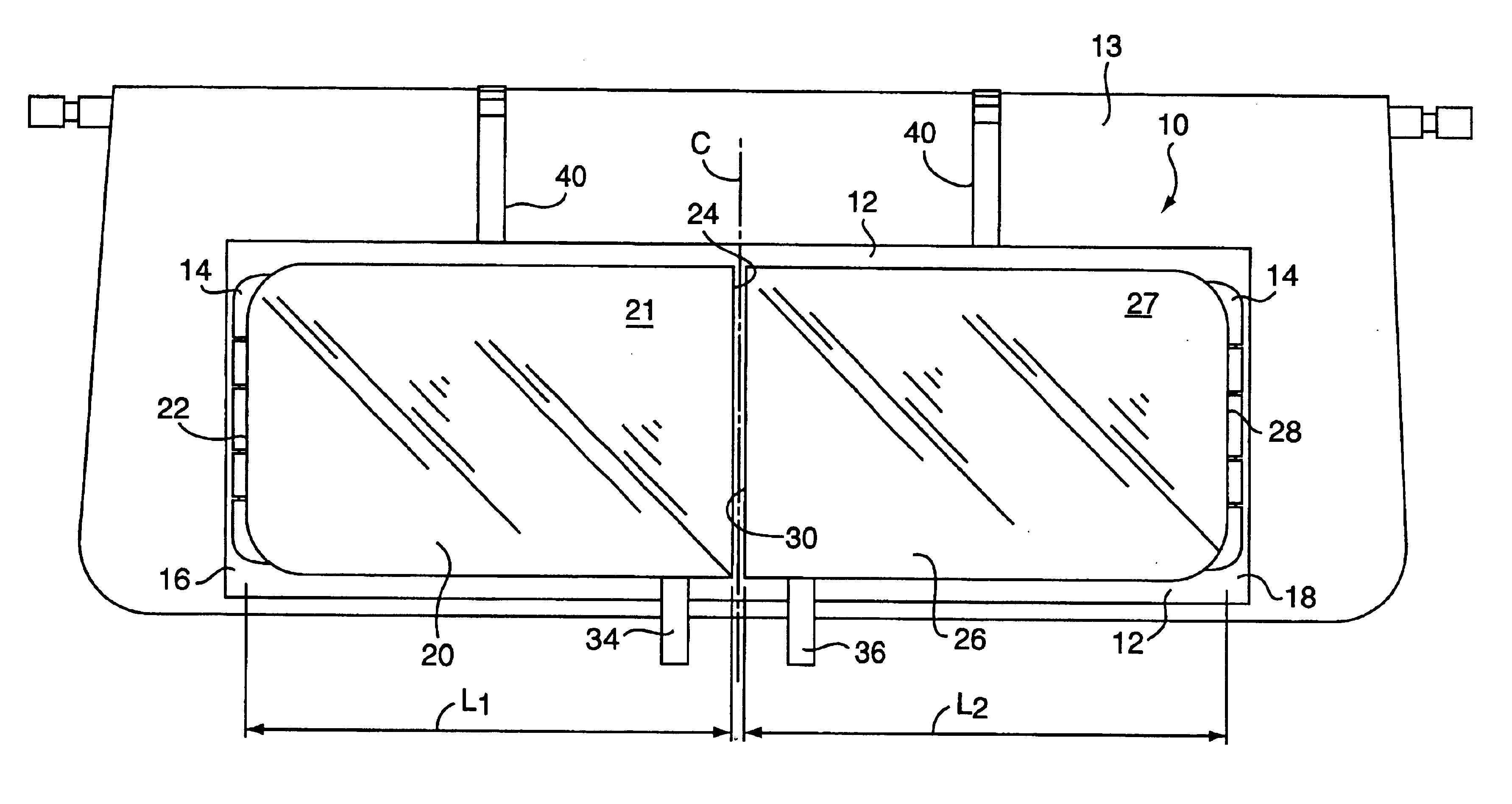
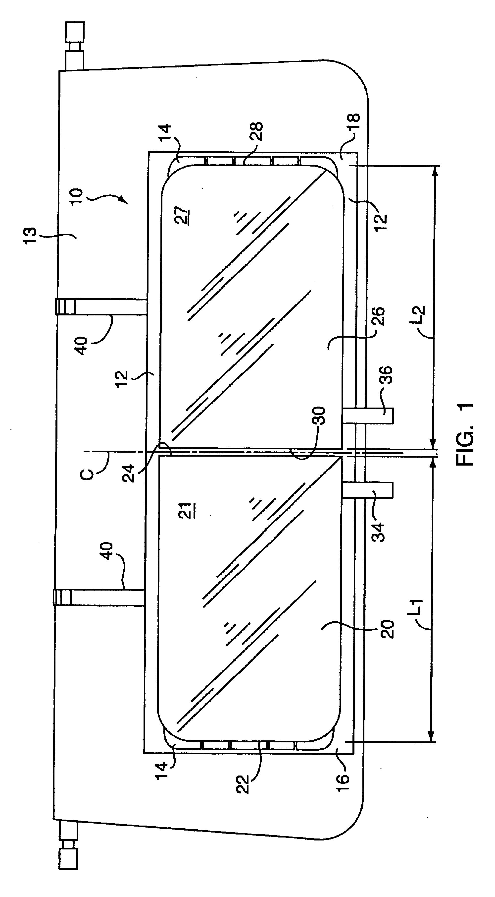
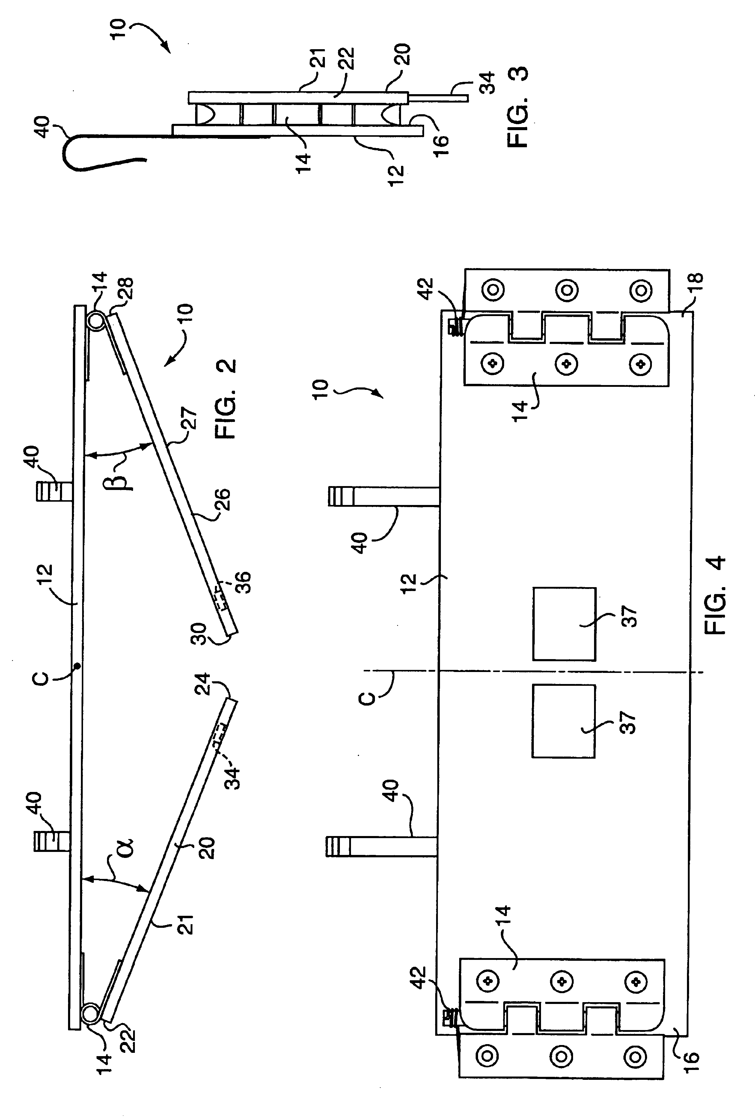
[0022]As shown in FIG. 1, the present invention is directed to a multi-view mirror generally designated by the reference number 10. The multi-view mirror 10 includes a mirror frame 12 having a pair of hinges 14 attached to outwardly opposing first and second outer edges 16 and 18 respectively, of the mirror frame. A first mirror 20 having a reflective surface 21, has an outward edge 22 pivotably mounted to the first outer edge 16 of the mirror frame 12 via one of the hinges 14 and an inward edge 24 disposed inwardly of the outward edge 22 near a center “C” of the mirror frame 12. A second mirror 26 having a reflective surface 27, has an outward edge 28 pivotably mounted to the second edge 18 of the mirror frame 12 with a hinge 14. The second mirror 26 also has an inward edge 30 disposed inwardly of the outward edge 28 near the center “C” of the mirror frame 12.

[0023]Still referring to FIG. 1, adjustment handles 34 and 36 are attached near the inward edges 24 and 30 of the first and ...


PUM


Abstract

The present invention provides a multi-view mirror having a mirror frame including an inwardly disposed center and two outwardly disposed mirror mounting elements attached to the frame on opposite sides of the center. The multi-view mirror includes a first mirror having an outward edge pivotally mounted to one of the mounting elements of the frame and an inward edge disposed inwardly of the outward edge near the center of the frame and a second mirror having an outward edge pivotally mounted to one of the mounting elements of the frame and an inward edge disposed inwardly of the outward edge near the center of the frame. The first mirror and second mirror are angularly positionable relative to the frame wherein at least one of the first and second mirrors are pivoted about one of the mounting elements to form a generally angled mirror.

Description

CROSS REFERENCE TO RELATED APPLICATIONS[0001]This application claims priority to provisional patent application Ser. No. 60 / 416,754, file Oct. 7, 2002 and titled “Multi-View Visor Mirror”. The disclosure of the provisional application is incorporated in its entirety herein by reference.FIELD OF THE INVENTION[0002]The present invention generally relates to a mirror, and more particularly to an adjustable multi-view mirror for extending the field of view of a user thereof.BACKGROUND OF THE INVENTION[0003]Multi-view mirrors for extending the view of a user are known in the art, however, most prior art mirrors of this type are designed to be mounted on a rear view mirror of an automobile and either replace the original mirror or mount thereto extending the view thereof rearward of the user of the mirror. Additionally, convex mirrors are known to extend the field of view of a user, however convex mirrors also distort the viewed objects and reduce a perception of distance.[0004]Further, m...

Claims


Application Information

Patent Timeline
Patent Type & Authority Patents(United States)
IPC IPC(8): B60R1/08G02B7/182
CPCB60R1/081G02B7/1821Y10S359/903
Inventor SAWYER, BRADLEY
Owner SAWYER BRADLEY
Why Eureka
Try Eureka